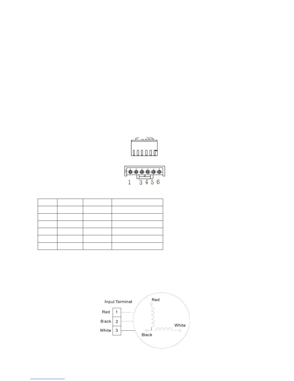
2) Power on and when the unit is in standby, measure the voltage of pin4-5 in feedback signal
connector. If the value is not 5V, change the PCB. Otherwise, go to step 3.
3) Rotate the fan by hand, measure the voltage of pin1-5, pin 2-5 and pin 3-5 in feedback signal
connector. If any voltage is not positive voltage fluctuation, the fan motor must has problems and
need to be replaced.
Index2:
1: Indoor or Outdoor DC Fan Motor(control chip is in fan motor)
Power on and when the unit is in standby, measure the voltage of pin1-pin3, pin4-pin3 in fan motor
connector. If the value of the voltage is not in the range showing in below table, the PCB must has
problems and need to be replaced.
DC motor voltage input and output
2. Indoor AC Fan Motor
Power on and set the unit running in fan mode at high fan speed. After running for 15 seconds,
measure the voltage of pin1 and pin2. If the value of the voltage is less than 100V(208~240V power
supply)or 50V(115V power supply), the PCB must has problems and need to be replaced.
 Loading...