19
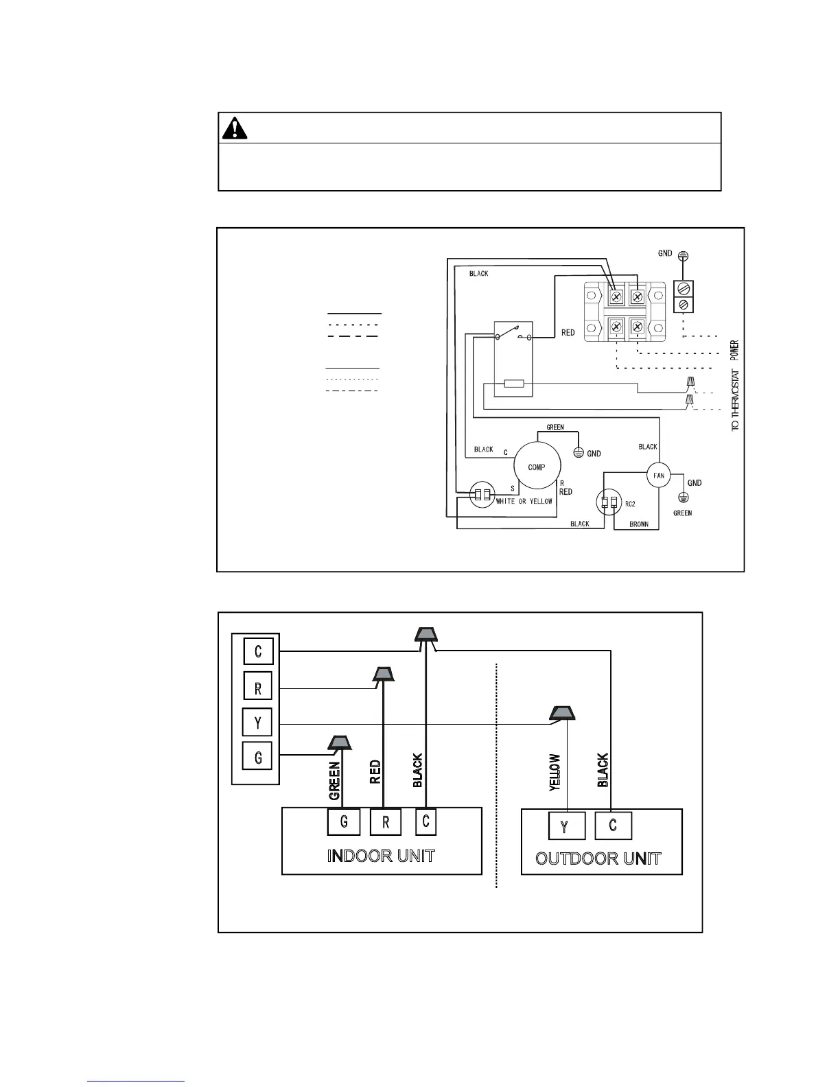
10.0 WIRING DIAGRAM
CAUTION
These units must be wired and installed in accordance with all National and
Local Safety Codes.
Fig.12 Outdoor Unit Wiring Diagram for A/C Systems(208/230V 1P 60Hz).
CCCOMPRESSORCONTACTOR
RC1RUNCAPACITOR1
RC2RUNCAPACITOR2
COMPCOMPRESSOR
LINEVOLTAGE
FACTORYSTANDARD
FIELDINSTALLED
OPTIONAL
LOW
FACTORY
VOLTAGE
FACTORYSTANDARD
FIELDINSTALLED
FACTORYOPTIONAL
USECOPPERCONDUCTORSONLY
WARNING:
CABINETMUSTBEPERMANMENTLY GROUNDED
ANDALLWIRINGTOCONFORMTO I.E.C, N.E.C,
C.E.C, C.L.C, ANDLOCALCODESAS APPLICABLE
REPLACEMENTWIREMUSTBETHESAMEGAUGE
AND INSULATIONTYPEASORIGINALWIRE.
ORANGE
A2
A1
T1
L1
BLACK
YELLOW
C
Y
RC1
L1L2
CC
L1
L2
GND
THERMOSTAT
C
Y
R
G
INDOOR UNIT
OUTDOOR UNIT
G
C
Y
R
C
Fig.13 Control Wiring for A/C Systems.
Suggestion: When choosing a thermostat, choose KJR-25B or a non-programmable
electric thermostat series . Please refer to thermostat electrical manual for wiring
schematic.
Terminal Block