Atom B Series VRF 50/60Hz
41
Part 5
-
Electrical Components and Wiring Diagrams
2.2.3 System check button
On pressing Spot check button, the parameters listed in Table 5-2.6 will be displayed in sequence.
Table 5-2.7: 28/36/42/48/56/60 model system check
Parameters displayed on DSP
Actual value = value displayed
Operating fan speed level
Total capacity requirement of indoor units
Total capacity requirement for the modified ODU
T3 Condenser temperature(°C)
Actual value = value displayed
T4 Outdoor ambient temperature(°C)
Actual value = value displayed
TP discharge temperature(°C)
Actual value = value displayed
TF invert module Temperature(°C)
Actual value = value displayed
TL refrigerant cooling tube temperature (°C)
Actual value = value displayed
Actual value = value displayed× 8
Actual value = value displayed
Inverter compressor current (A)
Actual value = value displayed
Actual value = value displayed
Actual value = value displayed
Indoor heat exchanger pipe (T2/T2B) average temperature (°C)
Actual value = value displayed
T2A condenser temperature
Actual value = value displayed
Actual value = value displayed
ODU address in the centralized control
system
Last 10 times error protection code
4
Notes:
1. Operating mode:
0: standby; 2: cooling; 3: heating; 4: forced cooling.
2. The fan speed index is related to the fan speed in rpm and can take any integer value in the range 0 (0-off) to 15 (fastest). Please refer to Table 4-1.3
note 2 in Part 4.
3. Priority mode:
0: first ON priority; 1: cooling priority; 2: Automatic selection of priority mode; 3: heating only; 4: cooling only; 5: heating priority
4. “nn” is displayed if no error or protection events have occurred since start-up; it displays all error protection code if the number of error protection
codes are less than 10 since start-up.
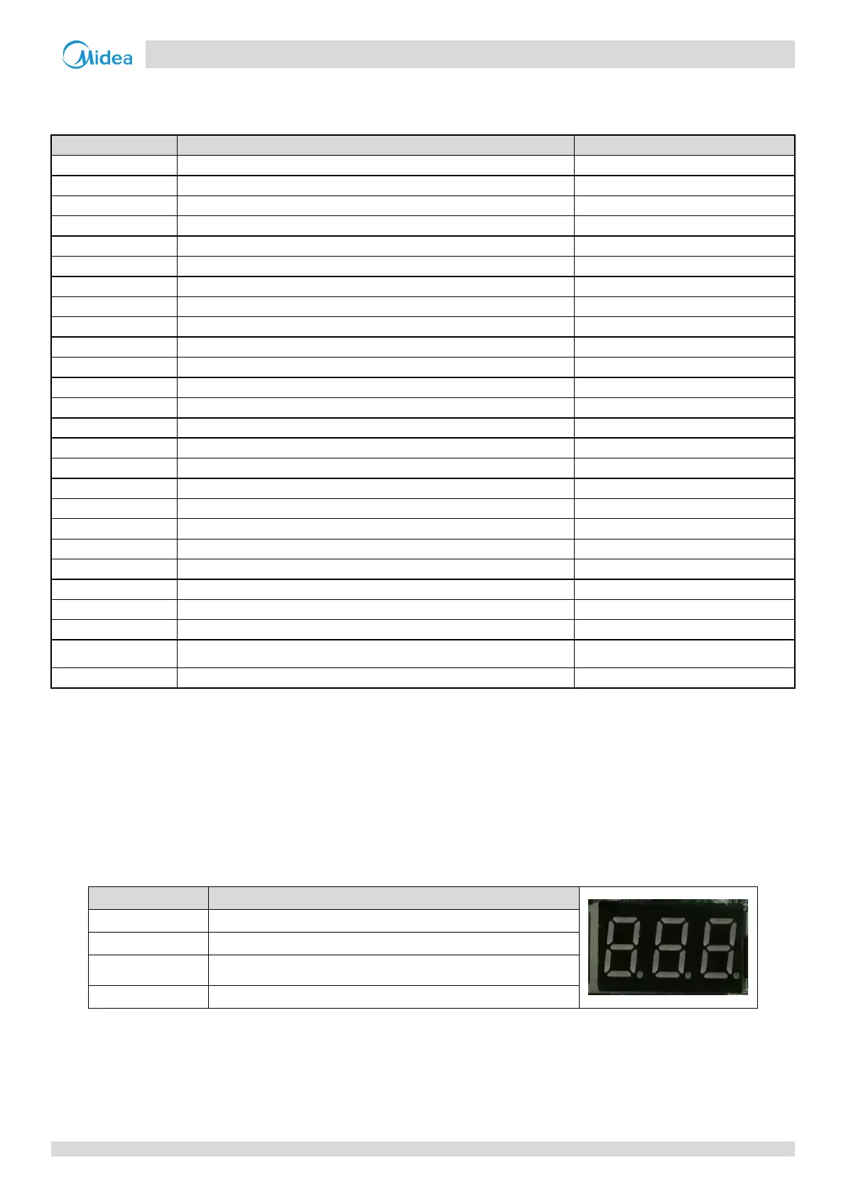
2.2.4 Digital display output
Table 5-2.8: Digital display output in different operating states
Parameters displayed on DSP
The number of indoor units in communication with the outdoor unit
 Loading...