Installation
Page 39
3.6 Connect signal and power cable
3.6.1 Before performing electrical work, read
these regulations
1. All wiring must comply with local and national electrical
codes, and must be installed by a licensed electrician.
2. All electrical connections must be made according to
the Electrical Connection Diagram located on the panels of
the indoor and outdoor units.
3. If there is a serious safety issue with the power supply,
stop work immediately. Explain your reasoning to the
client, and refuse to install the unit until the safety issue is
properly resolved.
4. Power voltage should be within 90-110% of rated
voltage. Insufficient power supply can cause malfunction,
electrical shock, or fire.
5. If connecting power to fixed wiring, install a surge
protector and main power switch with a capacity of 1.5
times the maximum current of the unit.
6. If connecting power to fixed wiring, a switch or circuit
breaker that disconnects all poles and has a contact
separation of at least 1/8in (3mm) must be incorporated
in the fixed wiring. The qualified technician must use an
approved circuit breaker or switch.
7. Only connect the unit to an individual branch circuit
outlet. Do not connect another appliance to that outlet.
8. Make sure to properly ground the air conditioner.
9. Every wire must be firmly connected. Loose wiring
can cause the terminal to overheat, resulting in product
malfunction and possible fire.
10. Do not let wires touch or rest against refrigerant
tubing, the compressor, or any moving parts within the
unit.
11. If the unit has an auxiliary electric heater, it must be
installed at least 1 meter (40in) away from any combustible
materials.
12. BEFORE PERFORMING ANY ELECTRICAL OR WIRING
WORK, TURN OFF THE MAIN POWER TO THE SYSTEM.
3.6.2 Connect signal and power cable
The signal cable enables communication between the
indoor and outdoor units. You must first choose the right
cable size before preparing it for connection.
Cable Types:
• Indoor Power Cable (if applicable): H05VV-F or
H05V2V2-F
• Outdoor Power Cable: H07RN-F
• Signal Cable: H07RN-F
Table: Minimum Cross-Sectional Area able of Power and
Signal Cables
Rated Current of
Appliance (A)
Nominal Cross-Sectional
Area (mm²)
> 3 and ≤ 6 0.75
> 6 and ≤ 10 1
> 10 and ≤ 16 1.5
> 16 and ≤ 25 2.5
> 25 and ≤ 32 4
> 32 and ≤ 40 6
1. Prepare the cable for connection:
• Using wire strippers, strip the rubber jacket from both
ends of signal cable to reveal about 40mm (1.57in) of
the wires inside.
• Strip the insulation from the ends of the wires.
• Using wire crimper, crimp u-type lugs on the ends of
the wires.
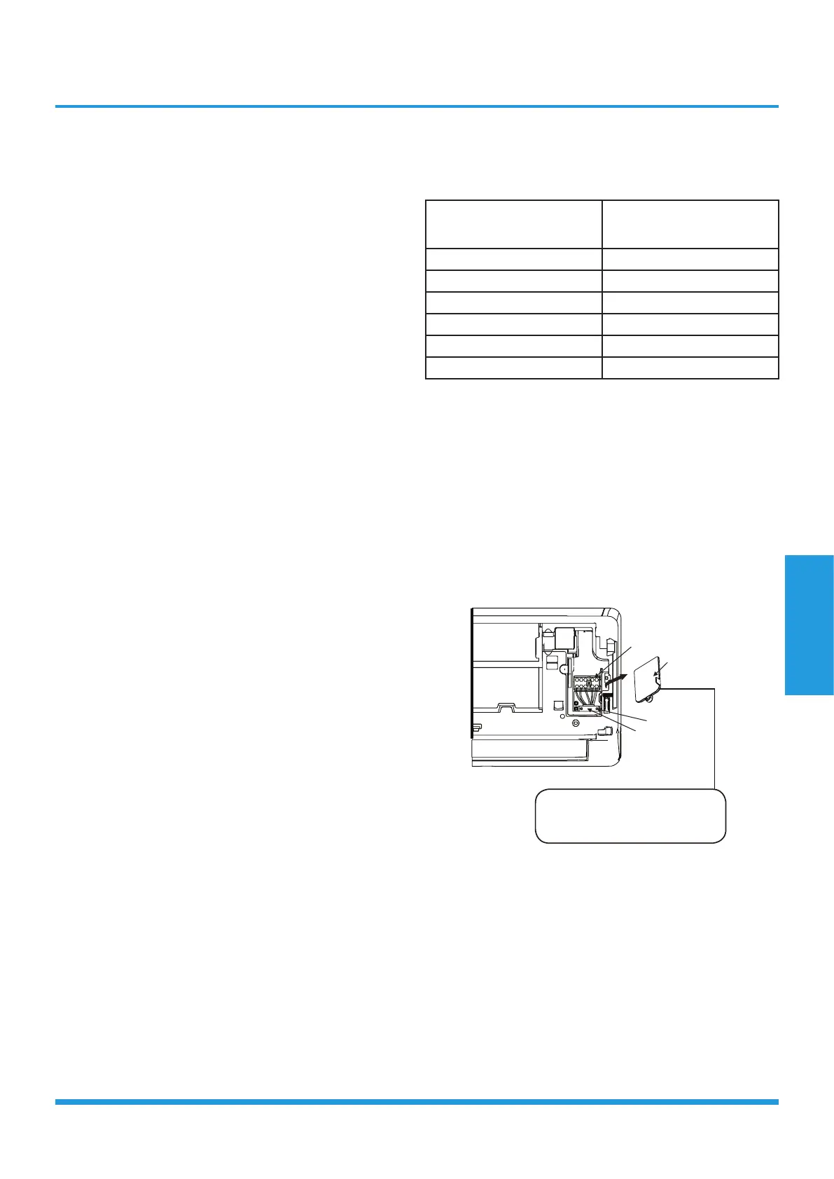
2. Open front panel of the indoor unit.
3. Using a screwdriver, open the wire box cover on the
right side of the unit. This will reveal the terminal block.
Terminal block
Wire cover
Screw
Cable clamp
The Wiring Diagram is located
on the inside of the indoor unit’s
wire cover.
4. Unscrew the cable clamp below the terminal block and
place it to the side.
5. Facing the back of the unit, remove the plastic panel on
the bottom left-hand side.
6. Feed the signal wire through this slot, from the back of
the unit to the front.
7. Facing the front of the unit, match the wire colors with
the labels on the terminal block, connect the u-lug and
and firmly screw each wire to its corresponding terminal.
8. After checking to make sure every connection is secure,