EasyManua.ls Logo

Midea CE-LRSJF-V120/N1-610 User Manual

Midea CE-LRSJF-V120/N1-610
58 pages
To Next Page IconTo Next Page
Page #1 background imageLoading...
Page #1 background image
MCAC-RTSM-2012-01 M-thermal Technical Manual(part 1)
1
Midea M-thermal
Heat Pump Water Heater
Technical Manual
Midea reserves the right to discontinue, or change at any time, specifications or designs without notices and
without incurring obligations.
CE-LRSJF-V120/N1-610
CE-LRSJF-V100/N1-610
CE-LRSJF-V80/N1-310
CE-LRSJF-V60/N1-310
CE-LRSJF-V80/N1-310-B
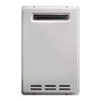
Outdoor unit
CE-LSX-300XP/D30B11
CE-LSX-200XP/D30B11
CE-LSX-150XP/D30B7
CE-LSX-300XP/SD15B11
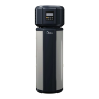
Water tank
CE-SMK-120/CD30GN1
CE-SMK-100/CD30GN1
CE-SMK-80/CD30GN1
CE-SMK-60/CD30GN1
CE-SMK-80/CSD80GN1
Indoor unit
CE-TMK-01
Solar kit

Table of Contents

Questions and Answers:

Midea CE-LRSJF-V120/N1-610 Specifications

General IconGeneral
ModelCE-LRSJF-V120/N1-610
CategoryWater Heater
TypeStorage
Capacity120L
Power2000W
Rated Voltage220V
Rated Frequency50Hz
MountingVertical
Heating MethodElectric
Protection FeaturesOverheat Protection

Summary

Part 1 System Outline

1. Measurements

Details physical dimensions, weight, and power supply for various unit types.

2. External Appearance

Shows images of outdoor, indoor, and solar kit units for visual identification.

3. Nomenclature

Explains the meaning of codes and characters in model names for different unit types.

4. Features

Highlights key features like safety, operating modes, environmental friendliness, and efficiency.

5. Specifications

Provides comprehensive specifications for outdoor, indoor units, water tanks, and solar kits.

6. Performance Data

Presents heating and cooling performance data across various operating temperatures.

7. Wiring Diagrams

Illustrates electrical connection diagrams for outdoor and hydraulic indoor units.

8. Dimensions

Shows detailed physical dimensions for outdoor and hydraulic indoor units.

9. Installation and Service Space

Specifies requirements for installation location and necessary service clearance.

10. Exploded Views

Provides exploded diagrams and parts lists for outdoor and hydraulic indoor units.

11. Accessories

Lists all included accessories categorized by unit type.

12. Functional Diagrams

Shows complete system diagrams and electrical connection details.

Part 2 Trouble Shooting

1. Normal Phenomenon

Describes normal operational behaviors that might appear unusual.

2. System Protection

Explains common protection mechanisms and their triggers for the system.

3. Trouble and Causes

Lists common symptoms, their causes, and initial troubleshooting steps.

4.1 Outdoor Unit Malfunction Codes

Details malfunction codes for the outdoor unit and their corresponding troubleshooting.

4.2 Hydraulic Indoor Unit Malfunction Codes

Details malfunction codes for the hydraulic indoor unit and their corresponding troubleshooting.

Part 3 Test Running and Maintenance

1. Pre-test and Test Running

Guides through checks and procedures before initial unit start-up.

2. Setting the Pump Speed

Explains how to select and adjust the pump speed for optimal system performance.

3. Field Settings

Details how to configure system parameters based on installation and user needs.

4. Maintenance

Outlines regular checks and maintenance tasks to ensure optimal unit availability.

Related product manuals