DLFSAB and DLFLAB: Service Manual
Manufacturer reserves the right to change, at any time, specifications and designs without notice and without obligations.
11
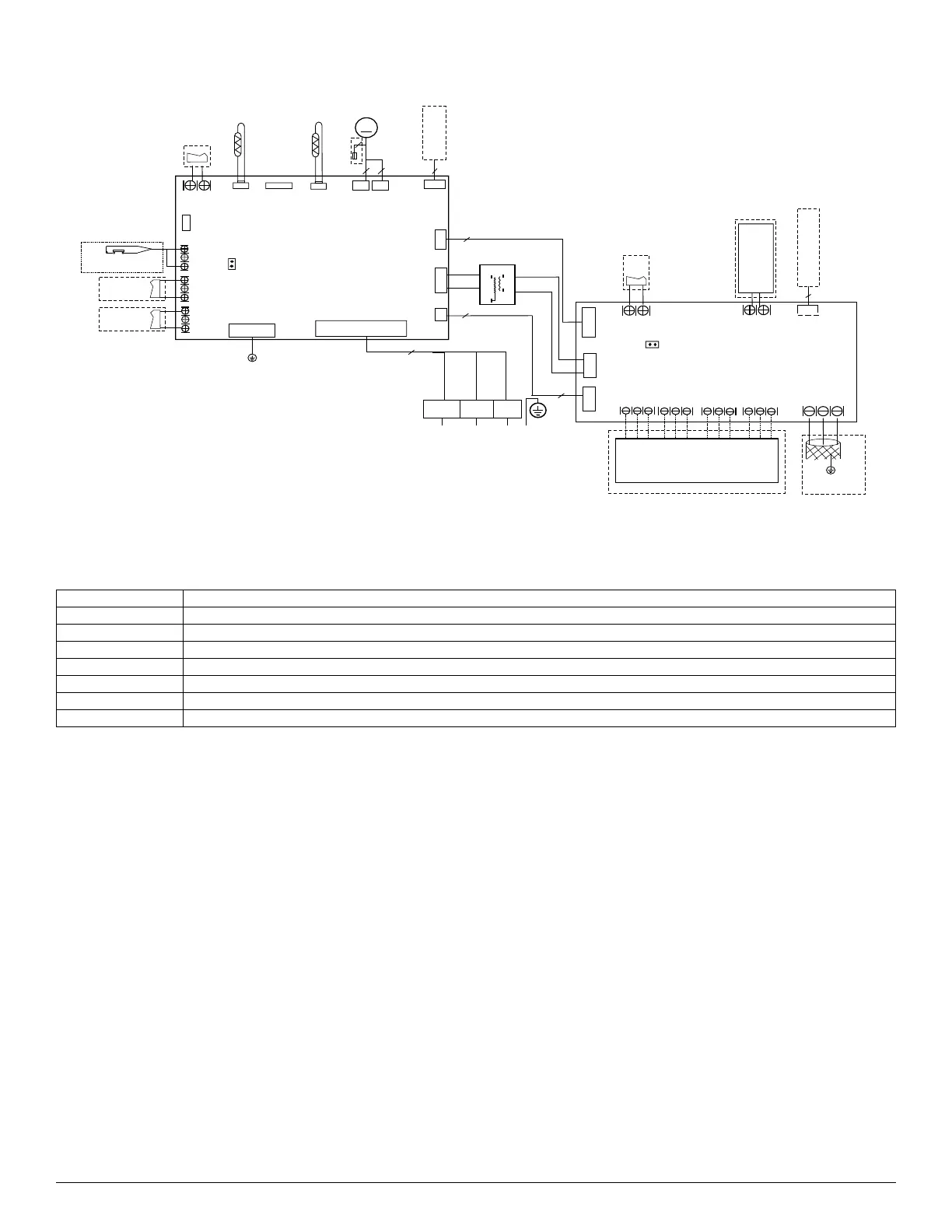
WIRING DIAGRAMS (CONT)
Fig. 16 — Wiring Diagram Sizes 36K - 60K Light Commercial Models
Table 4 — Wiring Diagram Sizes 36K - 60K Light Commercial Models
CODE PART NAME
ECM Indoor ECM Motor
CAP Indoor Fan Capacitor
FAN Indoor Fan Motor
T1 Room Temperature Sensor
T2 Coil Temperature Sensor
T2A Indoor Coil Inlet Temperature Sensor
T2B Indoor Coil Outlet Temperature Sensor
INDOOR UNIT
MAINBOARD
Y/G
Cn1 8
CN2 3
Alarm
CN3 3
work
6
Cn1 0
CN 5
WATER LEVEL
CN4 6
T1
ECM
Cn15
M
4(3)
3
Cn34
CN4 3
UVLE D
Output
BLU E
RED
RED
TRAN S
CN2 2
RED
CN 9
J1
CN2 9
T2
Cn1 2
3
HEATER
2
CN1 1
NL
L and N :230VAC
SWITCH
Output:5VDC
Output:24VAC
Output:5VDC
Output:5VDC
Output:220VAC
Output:12VDC
Output:24VAC
Output:15VDC
Output:220VAC
Output:24VAC
JR1
CN 5
CN 4
Cn 1
CN2
ON/OFF
Remote
Control
CN6 CN 9
W1
CN1 0
DH
CN1 1
CN7
2 WIR E WIRE
CONTROLLER
CN1 4
4
48 5 POR T
CN3
E Y X
To CCM
Comm.Bus
Output:24VAC
Output:24VAC
Output:+15VDC
Output:+12VDC
Output:+15VDC
Output:+12VDC
Output:+5VDC
Output:24VAC
Output:24VAC
Output:24VAC
Output:24VAC
DRY CONTACT
DRY CONTACT
L1
(
1)
L2
(
2)
S
(
3)
RE D
BLAC K
YELLO W
(WHITE )
TO OUTDOOR UNIT
3
S
S and N :0-24VDC
Y/ G
2
2
CN 6
Output:5VDC
CN2 1
Output:12VDC
T2 A
T2 B
R
C
L
G
Y1
Y/Y 2
B
W
W2
E/AU X
24V THERMOSTAT
 Loading...