DLFSAB and DLFLAB: Service Manual
Manufacturer reserves the right to change, at any time, specifications and designs without notice and without obligations.
10
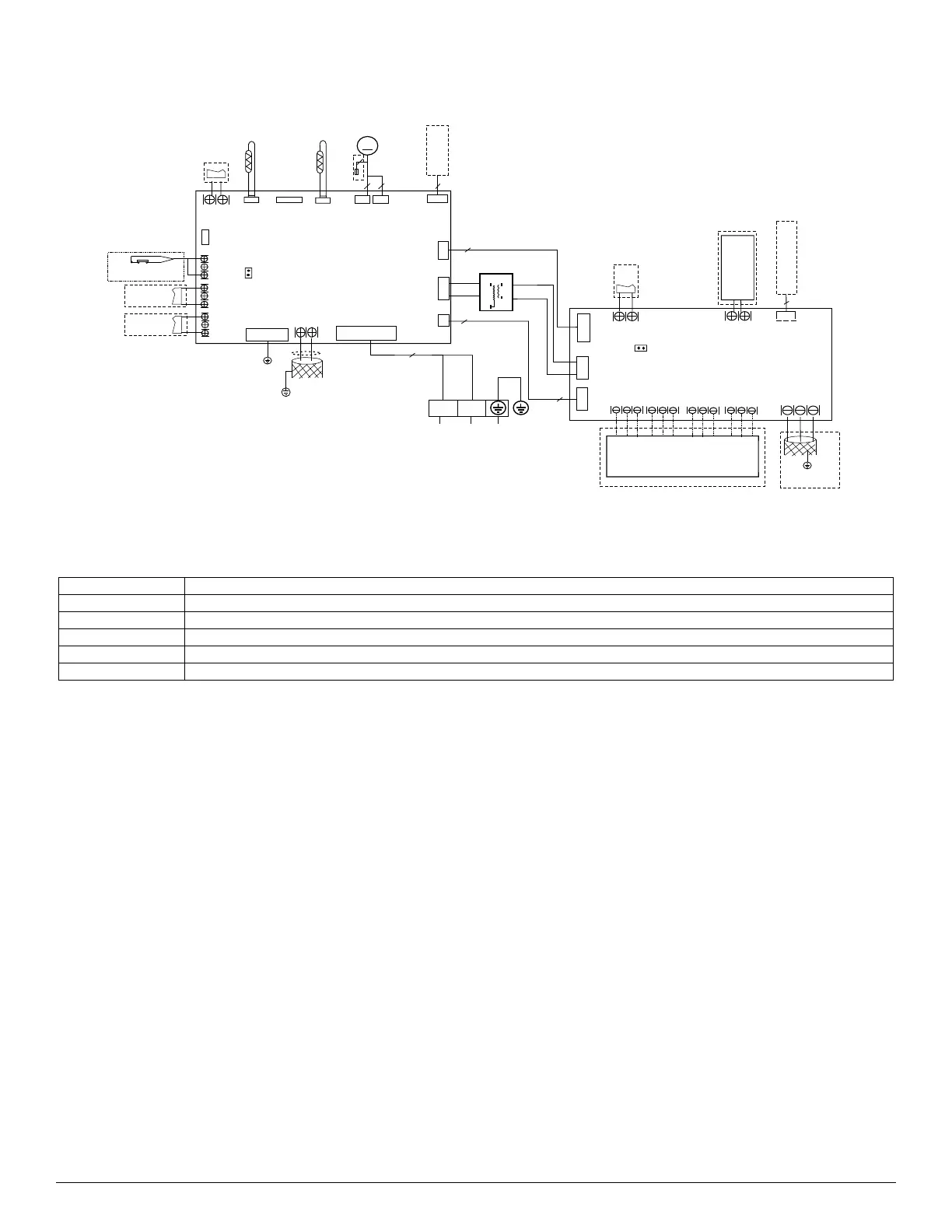
WIRING DIAGRAMS
Fig. 15 — Wiring Diagram Sizes 18K/24K/30K/36K - Non Light-Commercial Models
Table 3 — Wiring Diagram Sizes 18K/24K/30K/36K - Non Light-Commercial Models
INDOOR UNIT
MAINBOARD
Y/G
Cn1 8
CN2 3
Alarm
CN3 3
work
6
Cn1 0
CN 5
WATER LEVEL
CN4 6
T1
ECM
Cn15
M
4(3)
3
Cn34
CN4 3
UVLE D
Output
BLU E
RED
RED
TRAN S
CN2 2
RED
CN 9
J1
CN2 9
T2
Cn1 2
3
HEATER
2
CN1 1
L1
L2
RE D
BLAC K
TO OUTDOOR UNIT
OR POWER
2
NL
L and N :230VAC
SWITCH
Output:5VDC
Output:24VAC
Output:5VDC
Output:5VDC
Output:220VAC
Output:12VDC
Output:24VAC
Output:15VDC
Output:220VAC
Output:24VAC
JR1
CN 5
CN 4
Cn 1
CN2
ON/OF F
Remot e
Contro l
CN6 CN9 CN1 0
CN1 1
CN7
2 WIR E WIR E
CONTROLLE R
CN1 4
4
48 5 POR T
CN3
E Y X
To CCM
Comm.Bu s
Output:24VAC
Output:24VAC
Output:+15VDC
Output:+12VDC
Output:+15VDC
Output:+12VDC
Output:+5VDC
Output:24VAC
Output:24VAC
Output:24VAC
Output:24VAC
Y/ G
DRY CONTACT
DRY CONTACT
T2B
T2A
CN 6
CN 21
Output:5VDC
2
2
Output:12VDC
S1 S2
CN2 0
COMMUNICATION
TO OUTDOOR UNIT
W1
DH
R
C
L
G
Y1
Y/Y 2
B
W
W2
E/AU X
24V THERMOSTAT
CODE PART NAME
ECM Indoor ECM Motor
T1 Room Temperature
T2 Coil Temperature Sensor
T2A Indoor Coil Inlet Temperature Sensor
T2B Indoor Coil Outlet Temperature Sensor
 Loading...