EasyManua.ls Logo

Midea DLFSDAH09XAK - User Manual

Midea DLFSDAH09XAK
26 pages
Print Icon
To Next Page IconTo Next Page
Loading...
Specifications subject to change without notice.
DLFSDA and DLFLDA
INSTALLATION INSTRUCTIONS
Ducted Style Ductless System − Sizes 09 to 58
Fig. 1 - Sizes 09−48
Fig. 2 - Size 58
NOTES:
Read the entire instruction manual before starting the installation.
Images are for illustration purposes only. Actual models may differ
slightly.
TABLE OF CONTENTS
PAGE
SAFETY CONSIDERATIONS 2.............................
PARTS LIST 3...........................................
SYSTEM REQUIREMENTS 4...............................
WIRING 4...............................................
DIMENSIONS 5..........................................
INSTALLATION CLEARANCES 7...........................
MAINTENANCE CLEARANCES 7..........................
INSTALLATION LOCATION REQUIREMENTS 8..............
INDOOR UNIT INSTALLATION 8...........................
EXTERNAL STATIC PRESSURE 12.........................
FAN PERFORMANCES AT VARYING STATIC PRESSURES 13....
ELECTRICAL DATA 21...................................
CONNECTION DIAGRAMS 21.............................
START−UP 24............................................
TROUBLESHOOTING 25..................................
Question and Answer IconNeed help?

Do you have a question about the Midea DLFSDAH09XAK and is the answer not in the manual?

Summary

Safety Considerations

General Safety Precautions

Essential safety guidelines for installation and servicing personnel.

Electrical Shock Hazard Warning

Warning about significant electrical shock risk during installation and service.

Explosion Hazard Warning

Caution against using air or oxygen for leak testing, which can cause explosions.

Equipment Damage Hazard Caution

Warning regarding potential equipment damage from incorrect installation practices.

System Requirements and Wiring

Wiring for Sizes 09-24

Recommended connection methods for power and communication wiring.

Wiring for Sizes 36-58

Recommended connection methods for power and communication wiring.

Installation Clearances

Required Installation Clearances

Diagrams showing required clearances for installation and airflow.

Maintenance Clearances

Service Access Clearances

Required space for servicing components like blower motor and PCB.

Indoor Unit Installation Procedures

Unit Mounting and Support

Steps for securely mounting the indoor unit using hanger bolts and fasteners.

Condensate Pipe Installation

Condensate Piping Best Practices

Recommendations for condensate drain piping installation, slope, and insulation.

Condensate Drain and Lift Pump Installation

Horizontal Installation (Sizes 09-18)

Steps for installing external condensate lift pumps for specific unit sizes.

Horizontal Installation (Sizes 24-58)

Steps for connecting drain pipe to built-in condensate lift pumps.

Vertical Installation Considerations

Condensate Lift Pump Installation Details

Condensate Lift Pump Testing

Steps for testing the pump operation and checking for leaks.

External Static Pressure Settings

Static Pressure Adjustments

How to manually set static pressure or use automatic airflow adjustment.

Fan Performance Data

Static Pressure and Airflow Data

Tables detailing static pressure ratings and airflow rates for various models.

Fan Performance Charts (09 K)

Fan Performance Charts (12 K)

Fan Performance Charts (18 K)

Fan Performance Charts (24 K)

Fan Performance Charts (36 K)

Fan Performance Charts (48 K)

Fan Performance Charts (58 K)

Electrical Data

Connection Diagrams

Installation of Wiring and Piping

Start-Up and Testing Procedures

Test Operation Procedure

Steps for performing a test operation using the manual button.

Troubleshooting and Diagnostics

Indoor Unit Diagnostic Codes

Guide to understanding diagnostic codes displayed by indoor unit LEDs.

Overview

This document provides installation instructions for the DLFSDA and DLFLDA Ducted Style Ductless Systems, covering sizes 09 to 58. It includes safety considerations, parts lists, system requirements, wiring diagrams, dimensions, installation and maintenance clearances, indoor unit installation procedures, external static pressure settings, fan performance data, electrical data, connection diagrams, start-up instructions, and troubleshooting guides.

Function Description:

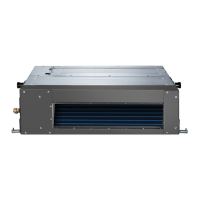
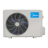
The DLFSDA and DLFLDA units are ducted style ductless systems designed for air conditioning. They are intended for indoor installation, typically within a false ceiling, and are connected to an outdoor unit. The system provides cooling and heating capabilities, with various fan speed settings and airflow adjustment options. Some models include a built-in condensate lift pump, while others require an external pump for horizontal installation. The units are designed to integrate with ductwork for air distribution.

Important Technical Specifications:

  • Refrigerant Line Length: Minimum 10 ft. (3 m) between indoor and outdoor units.
  • Pipe Sizes (Gas/Liquid):
    • 9K: Gas 3/8 in. (9.52 mm), Liquid 1/4 in. (6.35 mm)
    • 12K: Gas 1/2 in. (12.7 mm), Liquid 1/4 in. (6.35 mm)
    • 18K: Gas 1/2 in. (12.7 mm), Liquid 1/4 in. (6.35 mm)
    • 24K: Gas 5/8 in. (16 mm), Liquid 3/8 in. (9.52 mm)
    • 36K: Gas 5/8 in. (16 mm), Liquid 3/8 in. (9.52 mm)
    • 48K: Gas 5/8 in. (16 mm), Liquid 3/8 in. (9.52 mm)
    • 58K: Gas 3/4 in. (19 mm), Liquid 3/8 in. (9.52 mm)
  • Electrical Data (Indoor Fan):
    • 09K/12K: 1.11 FLA, 0.18 HP, 130 W
    • 18K/24K: 1.2 FLA, 0.27 HP, 200 W
    • 36K: 2.45 FLA, 0.56 HP, 420 W
    • 48K: 3.2 FLA, 0.75 HP, 560 W
    • 58K: 3.65 FLA, 0.952 HP, 1000 W
    • Voltage: 208/230-1-60 for all sizes.
  • Condensate Lift Pump:
    • External for sizes 09-18 (provided in a separate box for horizontal installation).
    • Built-in for sizes 24-58.
    • Capable of lifting water 29.5 in. (750 mm).
    • Highest point in piping should be close to the unit.
    • Drain piping slope: minimum 1/100 downward.
  • External Static Pressure (Rated Point):
    • 9K: 0.068 in. WG (17 Pa) to 0.176 in. WG (44 Pa)
    • 12K: 0.064 in. WG (16 Pa) to 0.20 in. WG (50 Pa)
    • 18K: 0.096 in. WG (24 Pa) to 0.392 in. WG (98 Pa)
    • 24K: 0.10 in. WG (25 Pa) to 0.528 in. WG (132 Pa)
    • 36K: 0.168 in. WG (42 Pa) to 0.62 in. WG (155 Pa)
    • 48K: 0.18 in. WG (45 Pa) to 0.64 in. WG (160 Pa)
    • 58K: 0.296 in. WG (74 Pa) to 0.8 in. WG (200 Pa)
  • Airflow at Rated Point (CFM/CMH):
    • 9K: High 353/600, Medium 282/480, Low 176/300
    • 12K: High 353/600, Medium 282/480, Low 176/300
    • 18K: High 529/900, Medium 450/765, Low 370/630
    • 24K: High 776/1320, Medium 694/1180, Low 435/740
    • 36K: High 1082/1840, Medium 912/1550, Low 703/1195
    • 48K: High 1229/2090, Medium 1032/1755, Low 715/1215
    • 58K: High 2157/3665, Medium 1710/2906, Low 1262/2145
  • Outside Air Connection: Knockout located downstream of the air filter. Booster fan (field supplied) recommended, powered by PCB board CN43 (max 200W input).

Usage Features:

  • Return Air Arrangement: Sizes 09-48 can be modified from rear return to bottom return by repositioning the air return flange and filters.
  • External Static Pressure Adjustment: Can be manually set to SP1, SP2, SP3, SP4 via the KSACN0501AAA Wired Controller, or automatically adjusted using the "AF" function.
  • Wired and Wireless Remote Control: Supports both wired and wireless remote controllers for operation. Wireless remote requires relocating the IR receiver for optimal line of sight.
  • Diagnostic Codes: Equipped with LEDs on both indoor and outdoor units to display diagnostic codes for troubleshooting.
  • Start-up Test Operation: Includes a procedure to perform a test operation after installation, checking functions like remote control, display panel lights, air deflection louver, and drain operation.
  • Communication Wiring:
    • Sizes 09-24: Field supplied 14/3 power/communication wiring from outdoor to indoor unit (4 wires: 2 high voltage AC, 1 communication, 1 ground). Shielded 14/2 stranded wire can be used for communication in high EMF areas.
    • Sizes 36-58: Field supplied power wiring from outdoor to indoor unit (3 wires: 2 high voltage AC, 1 ground). Separate shielded 16GA stranded control wire for communication.
    • All connections are sensitive to polarity.

Maintenance Features:

  • Clearances: Specific minimum clearances are required for installation and maintenance access (e.g., >11.8 in. (30 cm) for bottom return blower/motor service, >4 in. (10 cm) for depth of unit, >0.8 in. (2 cm) for side clearances).
  • Filter Service: Dedicated service access for air filter.
  • Blower/Motor Service: Access for servicing blower and motor components.
  • PCB Board Service: Access for servicing the PCB board.
  • Condensate Pump Maintenance: For built-in pumps (sizes 24-58), the pump can be detached by removing four screws and unplugging power/water level switch cables.
  • Drainage Test: Procedure to check for unhindered drainpipe and leaks by filling the drain pan with water.
  • Motor Maintenance: Instructions provided for taking off the ventilated panel, blower housing, and motor for maintenance.
  • Ceiling Access Panel: If installed above a hard lid ceiling, an access panel the length and width of the unit is recommended for removing blower components or the entire unit. Minimum dimensions for a single access panel are specified.

Midea DLFSDAH09XAK Specifications

General IconGeneral
BrandMidea
ModelDLFSDAH09XAK
CategoryAir Conditioner
LanguageEnglish

Related product manuals