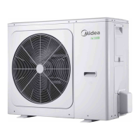
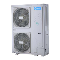
M‐ThermalSplit
18201909
MideaM‐ThermalSplitServiceManual
3.3 StartupControlforHeatingandDomesticHotWaterOperation
Table3‐3.1:Componentcontrolduringstartupinheatinganddomestichotwatermodes
Component
Wiringdiagram
label
4‐10kW Controlfunctionsandstates
Invertercompressor COMP ●
Compressor startup program selected according to
ambienttemperature
1
DCfanmotor FAN ● Fanrunatmaximumspeed
2
Electronicexpansionvalve EXV ●
Position(steps) from 0(fully closed) to 480(fully open),
controlled according to outdoor ambient temperature,
discharge temperature, suction superheat, compressor
speedandrefrigerantsystempressure
Four‐wayvalve 4‐WAY ● On
Notes:
1. RefertoFigure3‐3.1,Figure3‐3.2inPart3,3.2“CompressorStartupProgram”.
2. RefertoTable3‐4.1inPart3,4.6“OutdoorFanControl”.
3.4 StartupControlforCoolingOperation
Table3‐3.2:Componentcontrolduringstartupincoolingmode
Component
Wiringdiagram
label
4‐10kW Controlfunctionsandstates
Invertercompressor COMP ●
Compressor startup program selected according to
ambienttemperature
1
DCfanmotor FAN ● Fanrunatmaximumspeed
2
Electronicexpansionvalve EXV ●
Position(steps) from 0(fully closed) to 480(fully open),
controlled according to outdoor ambient temperature,
discharge temperature, suction superheat, compressor
speedandrefrigerantsystempressure
Four‐wayvalve 4‐WAY ● Off
4 NormalOperationControl
4.1 ComponentControlduringNormalOperation
Table3‐4.1:Componentcontrolduringheatinganddomestichotwateroperations
Component
Wiringdiagram
label
4‐10kW
Controlfunctionsandstates
Invertercompressor
COMP
●
Controlled according to load requirement from hydronic
system
DCfanmotor FAN
●
Controlled according to outdoor heat exchanger pipe
temperature
Electronicexpansionvalve EXV
●
Position(steps) from 0(fully closed) to 480 (fully open),
controlled according to outdoor ambient temperature,
discharge temperature, suction superheat, compressor
speedandrefrigerantsystempressure
Four‐wayvalve 4‐WAY
●
On
 Loading...
