Table 4-3
4.11.2 Table of diameter parameters of main inlet and outlet pipes
I&O manual
12
CAUTION
Please pay attention to the following items when installing multiple modules:
● Each module corresponds to an address code which cannot be repeated.
● Main water outlet temperature sensing bulb, target flow controller and auxiliary electric heater are under control of the main module.
● One wired controller and one target flow controller are required and connected on the main module.
● The unit can be started up through the wired controller only after all addresses are set and the aforementioned items are determined. The
wired controller is ≤500m away from the outdoor unit.
25≤Q≤50
50<Q≤80
80<Q≤130
135<Q≤210
210<Q≤325
325<Q≤510
510<Q≤740
740<Q≤960
DN40
DN50
DN65
DN80
DN100
DN125
DN150
DN200
4.11 Installation of multi-module water system pipeline
Multi-module combination installation involves special design of the unit, so relevant explanation is given as follows.
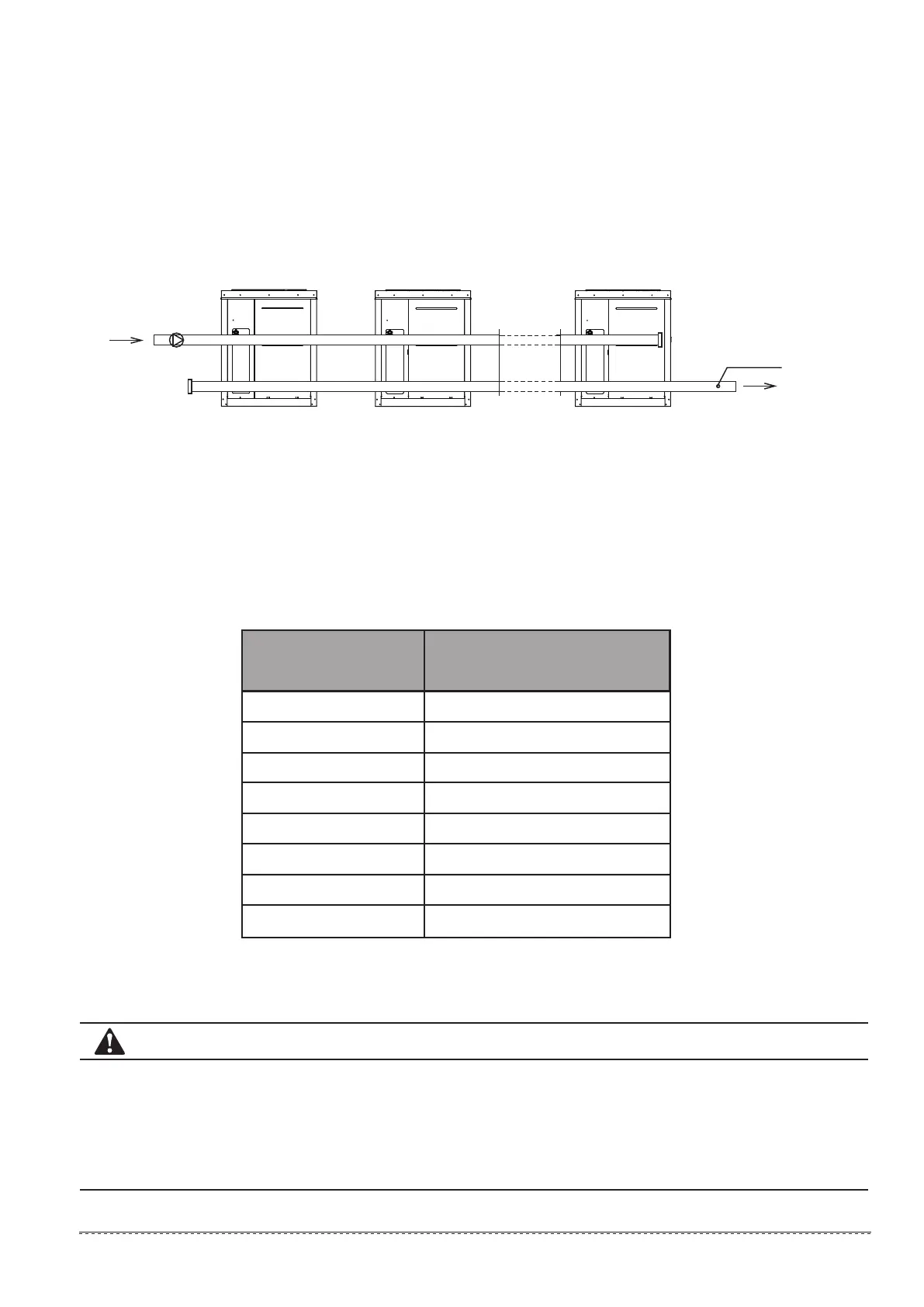
4.11.1 Installation mode of multi-module combination water system pipeline
1) MC-SU30-RN1L、MC-SU60-RN1L
Fig.4-7 (installation mode A: less than 16 modules)
No.n module
No.(n-1) address
No.1 moduleNo.(n-1) module
No.(n-2) address No.0 address
Total inlet and outlet water
pipe inside nominal diameter
Cooling capacity
Pump
Drill dead hole at the
position, and move the
total effluent temperature
sensor at No.0 address to
the position
 Loading...