Aqua Tempo Super II
28 201902
Midea Aqua Tempo Super II Engineering Data Book
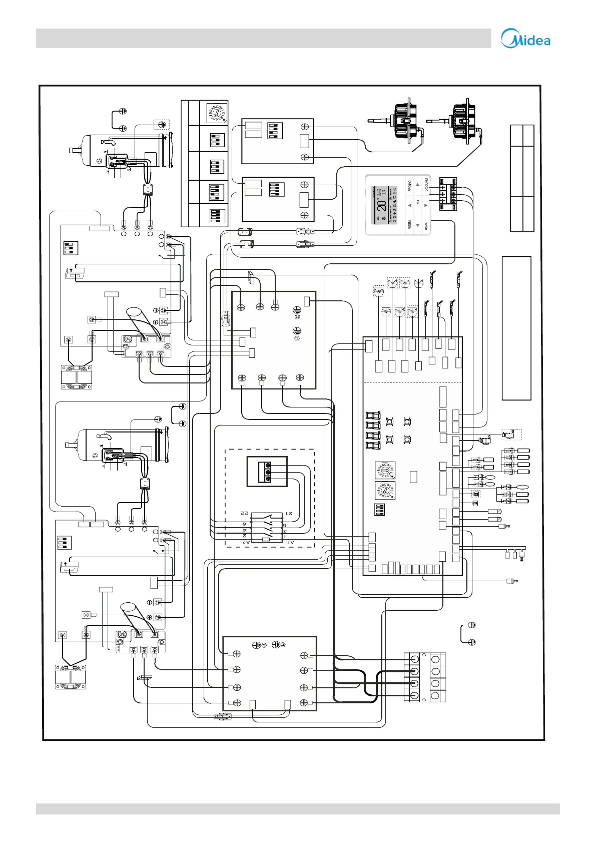
MC-SU60(M)-RN1L
Figure 2-4.2: MC-SU60(M)-RN1L
wiring diagram
16027100001031
Factory code Date Revision
December 7th, 2016
A
Note: 1.x represents for a system,1 is A system,
2 is B system.
2.Component in dash line is optional.
The wiring picture shown is for reference only,
actual product may vary.
380/415VAC 50/60Hz
Power in
L1
L3’
L2
L2’
L3
L1’
Red
White
Blue
R
e
d
W
hi
t
e
B
l
u
e
CN51
CN4
AC filter board B
CN36 CN37
CN38
CN40
CN41
CN42
5 4 3
2 1 0
7 6
N P
U
V
W
CN9(10)
CN1
CN4
CN6
CN3
CN13
Compressor
drive boardA
Brown
Brown
Blue
Blue
CN3
CN4
C_P
C_N
DC fan drive
board B
XS2
XS1
XP2
XP1
Fan B
FanA
W
V
U
Black
Red
CN53
O-FAN
CN52
O-FAN1
CN51
O-C1
Main board
ENC2
S5
ENC1
DSP1
DSP2
ON
CN38
L1 L2
CN69-1
CN45
SV3
CN17
eva-heat2
CN5_1
STF2
CN4
W-HEAT2
CN3
HEAT2
CN69
SV4_2
CN80
SV2
SV1
CN44
eva-heat1
CN5
STF1
CN4_1W-HEAT1
CN3_1
HEAT1
CN50
O-C
CN64
DEBUG
CN55
EXV1
CN71
P E Q
C N 6 9
Taf1 Tz/7 TP2 TP1
CN40CN41
CN57
EXV2
CN24
T4 T3
5V GND A2 B2 X Y
CN31
CN26
CN42
Tf2
L-YL1
Tf1
L3
L3’
L2
L2’
L1
L1’
Red
White
Blue
RedWhite
Blue
CN51
AC filter boardA
CN36
CN37
CN38
CN40 CN41
CN42
W
V
U
Blue
CN1
CT1
CT2
CN7
Black
Orange
Red
Red
Black
Black
Black
Black
R
e
d
B
l
u
e
Red
Black
Black
CN11
Red
Black
CN3
CN4
C_P
C_N
DC fan drive
board A
CN1
Red
Black
Blue
5 4 3
2 1 0
7 6
N P
U V W
CN10
CN1
CN4
CN6
CN3
CN13
Compressor
drive board B
CN7
Black
Red
Red
Black
Black
Black
Black
Brown
R
e
d
Brown
Black
Black
CN11
Red
Black
Red
Black
Blue
Yellow
Yellow
Yellow
Yellow
Yellow
Yellow
Reactor A
Compressor A
Reactor B
Compressor B
Rectifier A
Rectifier B
IC8
IC8
T4 T3
Water switch
OK
Up
Menu
Down
CN6
Th Taf2 Two Twi Tw
T7C2
Ferrite
core
N=1
N=1
P2
N2
Black
Ferrite core
P2
N2
Black
CN58
CN39
H-YL1
NUM_S
POWER
Green
Green
Front
Behind
Red
Red
CN15
Brown
CN2
CN1
Ferrite core
Brown
Blue
Brown
XS1
CN9
N
A
B
C
XP1
XS2
XP2
CN15
R
e
d
B
l
u
e
CN50
CN50
N1
Black
CN39
Ferrite
core
N=1
AC contactor
Black
R
e
d
W
h
i
t
e
B
l
u
e
R
e
d
SV4_1
CN49
O-D
CN60
Taf1 Tz/7 TP2 TP1
Twi Tw
Th Taf2 Two
L-YL1
H-YL1
CN62
CN47
PH-PRO
I1 I2
CN37CN59
N-ON
H-PRO
CN65
L-PRO
N-ON
Tf2
Tf1
EXVA
EXVB
XV
H-PRO-3
L-PRO
CN6
A B C N
Red
White
Blue
Black
CN39
CN43
N’
Black
Black
N1
CN72
CN30
09.20.2015
CN1
P E Q
P Q E
Green
Blue
Brown
CN3
CN6
PUMP
L 3 L 2 L 1
Gray
B
r
o
w
n
Black
B
r
o
w
n
Black
Gray
Red
Red
White
White
Blue
Black
Red
Black
Brown
Black
Blue
Blue
Orange
Orange
Orange
Red Red Red Red
CN19_L
CN19_N
CN21
CN2
Alarm
E-HEAT_L
E-HEAT_N
PUMP2
PUMP1
DC fan drive
board A
DC fan drive
board B
Compressor
drive board A
Compressor
drive board B
Main
board
ENC2
SW1
SW1
SW1
SW1
SW1 SW1 SW1
SW1
Default setting
ZR
ZR
1
2
3
4
1
2
3
4
1
2
3
1
2
3
1
2
3
4
1
2
3
4
CN48
Water switchCN44
CN70 DOOR-switch2
DOOR-switch1
CN45
CN46
ON/OFF
COOL/HEAT
1
2
3
1
2
3
H-PRO-1
H-PRO-2
 Loading...