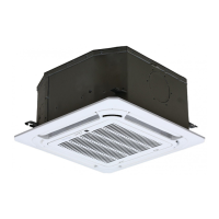
CN2(yellow)
CN1(red)
CN6(black)
CN3(yellow)
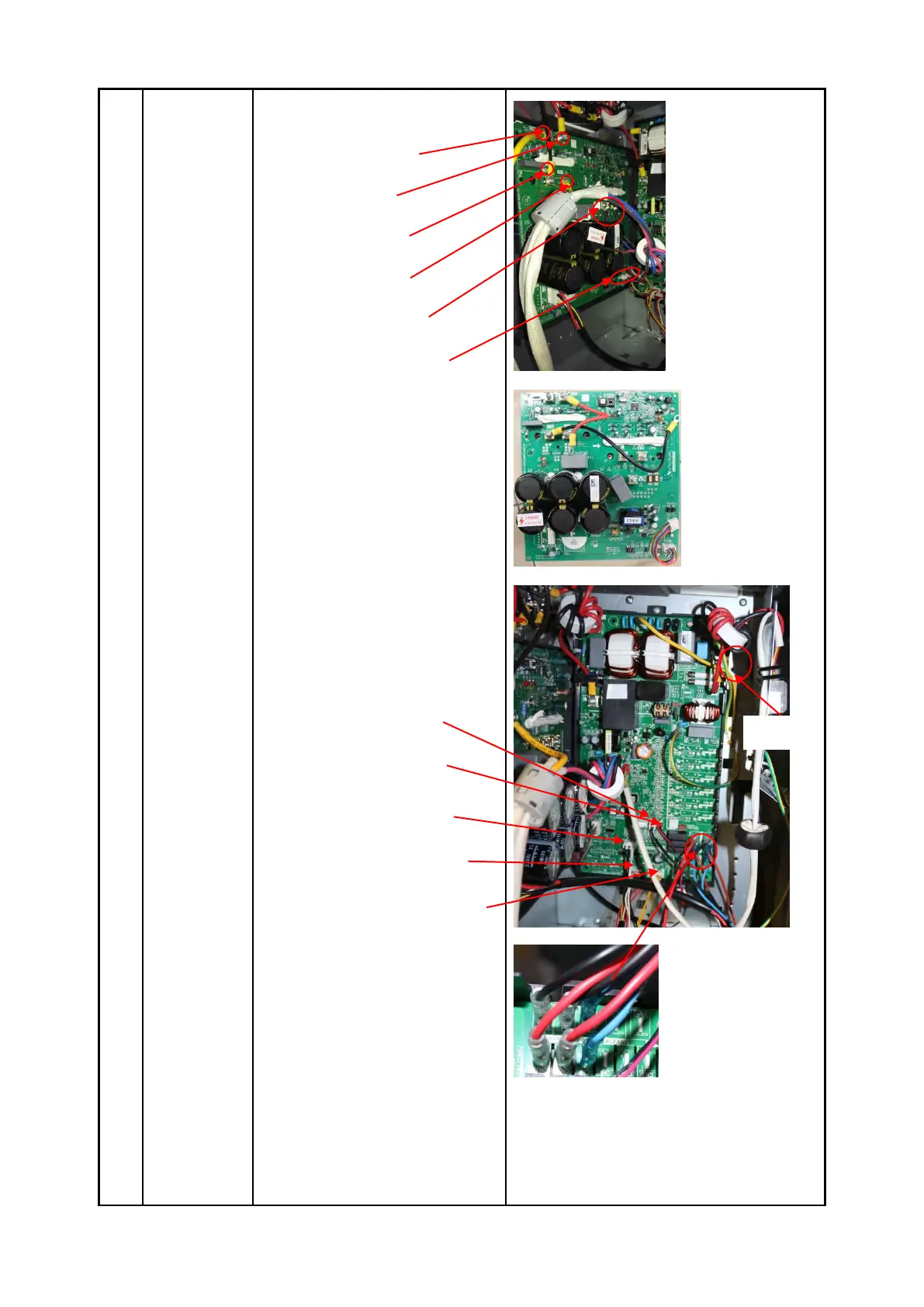
U、V、W(black)
CN9(10p,white)
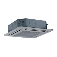
4) Remove the screws
fixing the IPM board and remove
the IPM board.
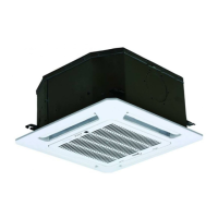
5) Disconnect the connectors
and wires connected from PCB
and other parts.
Connectors:
CN8: Discharge temperature sensor
(2p,white)
CN12:Heatsink temperature
sensor(2p,red)
CN9:T3/T4 temperature sensor
(2p/2p,white)
CN15: Electronic expansion valve
(6p,red)
CN10: High and low pressure switch
(2p/2p, white)
Wires:
CN17/CN18: 4-way valve (blue-blue)
CN19/CN20: connected to crankcase
heating cable. (black-red)
CN24/CN25: Electric heater of
chassis (orange-orange)
CN1:L-IN (red or white)
CN3:N-IN (black)
6) Disconnect the grounding
 Loading...