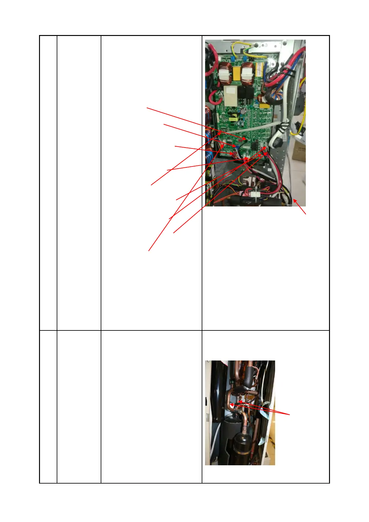
4) Disconnect the connectors
and wires connected from
PCB and other parts.
Connectors:
CN8: Discharge temperature sensor
(2p,black)
CN9:T3/T4 temperature sensor
(2p/2p,blue)
CN15/CN23: Electronic expansion
valve (6p,red)
CN10: High and low pressure switch
(2p/2p, white)
CN22:S1 and S2(1p/1p,red)
Wires:
CN17/CN18: 4-way valve (blue-blue)
CN19/CN20: connected to crankcase
heating cable. (black-red)
CN24/CN25: Electric heater of
chassis (black-red)
CN6(10p,white)
5) Remove the 4 screws and
unfix the 6 hooks and then
remove the main control
board.
How to remove the compressor.
1) Perform work of item 1 step
5~6 and item 2.
2) Extract refrigerant gas.
3) Remove the sound
insulation material and
crankcase heating cable.
4) Remove terminal cover of
compressor, and disconnect
wires of crankcase electric
 Loading...