R410A All DC Inverter V4+S Series 60Hz MCAC-VTSM-2015-09
94 Installation
1. Select indoor unit pipes from indoor unit to the nearest branch joint: a, b, c, d, e, f, g, h, i, j.
Refer to table 5, the pipes of a~j are Φ5/8(15.9)/ Φ3/8(9.53).
2. Select the main pipe L1, indoor unit main pipes L2~L9 and branch joints B~I:
The downstream indoor units of L3 are N1 and N2, with total capacity of 14×2=28kW(95.5kBtu/h). Refer to table 1, the indoor
unit main pipe L3 is Φ7/8(22.2)/ Φ3/8(9.53). The branch pipe assembly C is FQZHN-02D.
The downstream indoor unit of L4 is N3 and N4, with total capacity of 14×2=28kW(95.5kBtu/h). Refer to table 1, the indoor unit
main pipe L4 is Φ7/8(22.2)/ Φ3/8(9.53). The branch pipe assembly D is FQZHN-02D.
The downstream indoor unit of L7 is N6 and N7, with total capacity of 7.1×2=14.2kW(48.5kBtu/h). Refer to table 1, the indoor
unit main pipe L7 is Φ5/8(15.9)/ Φ3/8(9.53). The branch pipe assembly G is FQZHN-01D.
The downstream indoor units of L9 are N9 and N10, with total capacity of 5.6×2=11.2kW(38.2kBtu/h). Refer to table 1, the
indoor unit main pipe L9 is Φ5/8(15.9)/ Φ3/8(9.53). The branch pipe assembly I is FQZHN-01D.
The downstream indoor units of L2 are N1, N2, N3 and N4, with total capacity of 14×4=56 kW (191.1kBtu/h). Refer to table 1,
the indoor unit main pipe L2 is Φ1-1/8(28.6)/ Φ5/8(15.9). The branch pipe assembly B is FQZHN-03D.
The downstream indoor unit of L6 is N5, N6 and N7, with total capacity of 14+7.1×2=28.2kW(96.2kBtu/h). Refer to table 1, the
indoor unit main pipe L6 is Φ7/8(22.2)/ Φ3/8(9.53). The branch pipe assembly F is FQZHN-02D.
The downstream indoor units of L8 are N8, N9 and N10, with total capacity of 14+5.6×2=25.2kW(86kBtu/h). Refer to table 1,
the indoor unit main pipe L8 is Φ7/8(22.2)/ Φ3/8(9.53). The branch pipe assembly H is FQZHN-02D.
The downstream indoor units of L5 are N5, N6, N7, N8, N9 and N10, with total capacity of
14×2+7.1×2+5.6×2=53.4kW(182.2kBtu/h). Refer to table 1, the indoor unit main pipe L2 is Φ1-1/8(28.6)/ Φ5/8(15.9). The
branch pipe assembly E is FQZHN-03D.
3. Select main pipe L1 and branch joint A:
For outdoor units with capacity of 40HP, the equivalent length of all pipes in this system is larger than 295ft(90m), refer to table
2, the main pipe L1 is Φ1-1/2(38.1)/ Φ7/8(22.2), the branch pipe assembly A is FQZHN-04D.
The downstream indoor units of L1 are N1~N10, with total capacity of 14×6+7.1×2+5.6×2=109.4kW(373.3kBtu/h). Refer to
table 1, the main pipe L1 is Φ1-1/2(38.1)/ Φ3/4(19.1). So we finally select the larger pipeΦ1-1/2(38.1)/ Φ7/8(22.2) as main pipe
L1.
4. Outdoor unit connection pipe (g1, g2, g3, G1,L+M) selection (refer to table3, table 4)
The pipe g1 is connected to 10HP outdoor unit. Refer to table3, the diameter of g1 is Φ1(25.4) /Φ1/2(12.7).
The pipe g2 is connected to 14HP outdoor unit. Refer to table3, the diameter of g2 isΦ31.8(Φ1-1/4) /Φ15.9(Φ5/8).
The pipe g3 is connected to 16HP outdoor unit. Refer to table3, the diameter of g3 is Φ1-1/4(31.8)/ Φ5/8(15.9).
Refer to table3, the diameter of G1 isΦ38.1(Φ1-1/2)/ Φ3/4(19.1).
The quantity of combined outdoor units is three. Refer to table4, the outdoor branch assembly is L+M: FQZHW-03N1D.
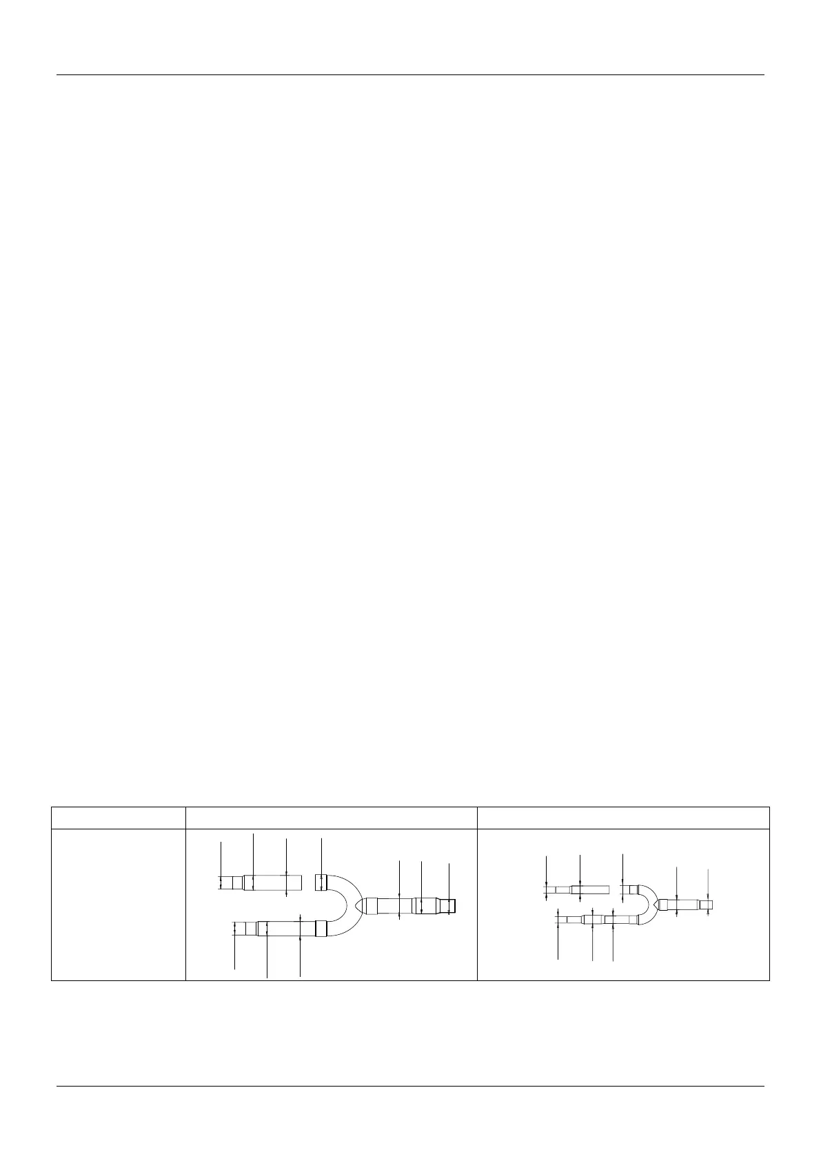
3.4 Branch joint dimension
3.4.1 Indoor branch joint dimension
ID:12.7
(ID:15.9)
OD:19.1
ID:19.1
OD:19.1
ID:19.1
ID:15.9
ID:12.7
(ID:15.9)
OD:19.1
OD:12.7
ID:9.5
ID:9.5
ID:6.4
OD:9.5
ID:6.4
OD:9.5
ID:9.5
 Loading...