Do you have a question about the Midea MDV-V80W/DN1 and is the answer not in the manual?
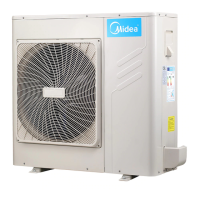
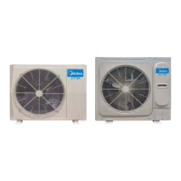
Details outdoor unit models, dimensions, weight, and power supply specifications.
Explains the naming convention for product model numbers and components.
Highlights key features like wide application, indoor unit variety, and capacity range.
Lists available indoor unit types (cassette, ducted, etc.) and capacities.
Provides detailed technical specs for outdoor units (electrical, physical data).
Shows physical dimensions of outdoor units for different models (mm).
Illustrates required outdoor unit clearance for installation and airflow.
Presents schematic diagrams of the refrigerant piping layout.
Shows electrical wiring diagrams for different models and component connections.
Outlines wiring requirements for field installation, including power and signal.
Lists cooling/heating capacity data for various temperature combinations.
Details electrical specs (voltage, current, motor output) for outdoor units.
Provides noise levels (dB(A)) and measurement heights for outdoor units.
Defines operating temperature ranges for cooling and heating.
Lists essential safety measures and considerations for installation.
Lists included installation fittings and manuals.
Covers guidelines for selecting installation space and positioning the outdoor unit.
Details refrigerant piping connection, allowable lengths, and level differences.
Explains electrical installation highlights and wiring selection criteria.
Specifies power and signal wiring for outdoor units based on capacity.
Provides instructions and cautions for the initial system test run.
Outlines measures to prevent and handle refrigerant leakage.
Details PCB port functions and voltages for 80/105 models.
Explains PCB parts, query instructions, and notes for different models.
Describes dial switch definitions for auto addressing and other functions.
Identifies and explains LED indicators on PCBs for different models.
Shows PCB layouts and identifies main components for different models.
Lists error codes, their content, and affected models for troubleshooting.
Provides step-by-step procedures for specific error codes (H0/E3, E2).
| Type | Split System |
|---|---|
| Cooling Capacity | 8.0 kW |
| Refrigerant | R410A |
| Indoor Unit Type | Wall Mounted |
| Power Supply | 220-240V, 50Hz |