MCAC-VTSM-2013-12 R410a Full DC Inverter Mini VRF
Troubleshooting 89
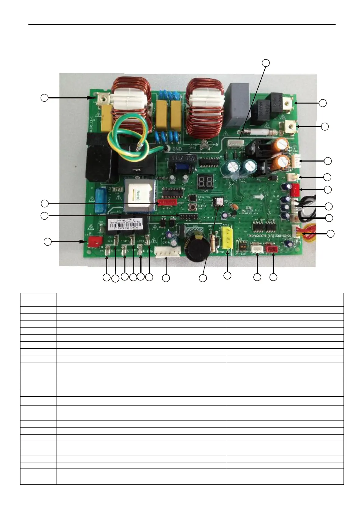
1. PCB ports instructions
80/105 model
PCB ports instruction
PCB power supply output port
The first pin on the left: DC12V
The other four pins: in dynamic change
Load output port (4-way valve)
Signal output of outdoor fan port
Power supply of outdoor fan port
Communication port between indoor units
Communication port between outdoor unit and indoor unit
Signal input port of system low pressure & high pressure detect
switch
DC0~5V (in dynamic change)
Discharge temperature detection port of the inverter compressor
DC0~5V (in dynamic change)
Outdoor temperature & condenser coil temperature detection port
DC0~5V (in dynamic change)
Communication port between PCB and PFC module
The first pin on the left: DC12V
The other four pins: in dynamic change
Communication port between PCB and IPM module
The first pin on the right: DC12V; the second
pin on the right:5V
4
5
6
7
8
9
10
11
13
14 15
16
17
18
19
20
21
2
3
12
22
23
1
24