MCAC-2008-11 Air-cooled Modular Chiller
46
1-1/4 26 13 75 68
1-1/2 29 20 105 94
2 34 17 120 105
2-1/2 60 34 210 188
3
2
68 30 288 275
4 128 64 412 360
5 225 113 750 652
6
3
345 172 1125 975
Note: Water flow switch can be installed outdoors without waterproof and horizontally or vertically. The
buffer pipes must be installed in front of and behind water flow switch and its length should be 5 times of pipe
diameter; since water flow switch cannot be got impact, so don’t install the fast closed valve at lower reaches
of it. If cannot avoid such thing, should use the throttle to protecting it.
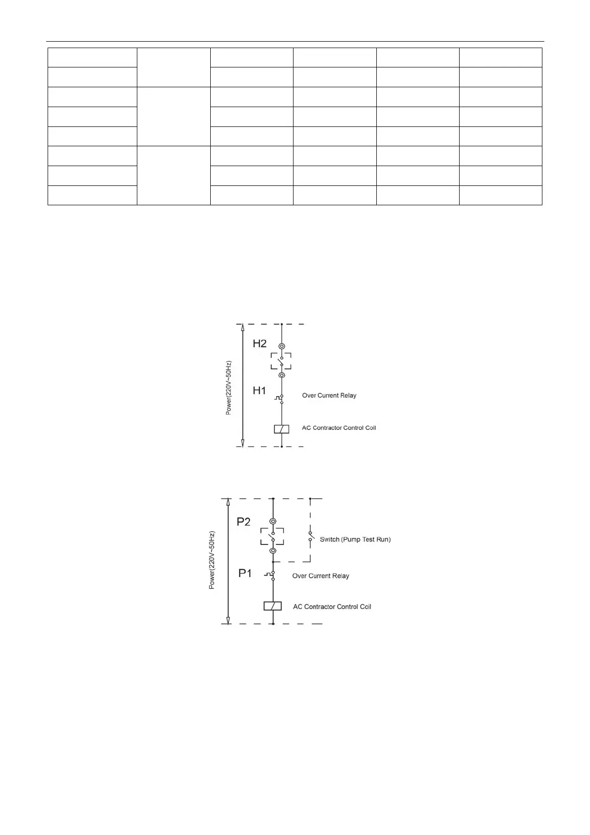
6. Auxiliary electric heater control wire connection (outfitting by users):
The control wire of AC contactor must pass the main unit’s terminals H1, H2. The reference diagram is as
follows:
7. Water pump control wire connection: the control wire of A/C contactor should through P1、P2 terminals of
main unit as follows.
8. Wiring of “ON/OFF” weak electric port: first, corresponding parallel connect the “ON/OFF” port of each
module’s electric control box (no more than 16) ,then, connect the “ON/OFF” signal (from the user’s timer) to
the “ON/OFF” port of main unit as follows.
 Loading...