MCAC-2008-11 Air-cooled Modular Chiller
67
of main modular unit; connect the 5 foot to “E ” communication port of main modular unit; and connect the 3
foot to “Q ” communication port of main modular unit. Wiring illustration as above.
Operation Description of LCD Touch Screen
The base conditions for using this LCD:
1) Voltage range: Input voltage: 24VDC±2%;
2) Power capacity: 15W,
3) Ambient temperature of using the LCD: 0℃~+50 . Ambient temperature for keeping the LCD: 0℃℃~+
60 . Ambient humidity for keeping the LCD: without frost 10%℃ ~90%RH.
4) Displaying way: 7”TFT LCD
Displaying color: 256 colors
Resolution: 480×236 pixels
LCD touch screen: Resistance type
Defective proof level: IP 65
Function description:
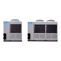
This LCD control system is configured by the LCD of Air Cooled Heat Pump and outdoor unit electricity
control system (At most 16 outdoor units could be connected). Configuration figure as follows:
This LCD centralized control the Air Cooled Heat Pump Modular Chiller, delivers various control orders or
setting functions to each unit system, as well as receives and displays operation data from units.
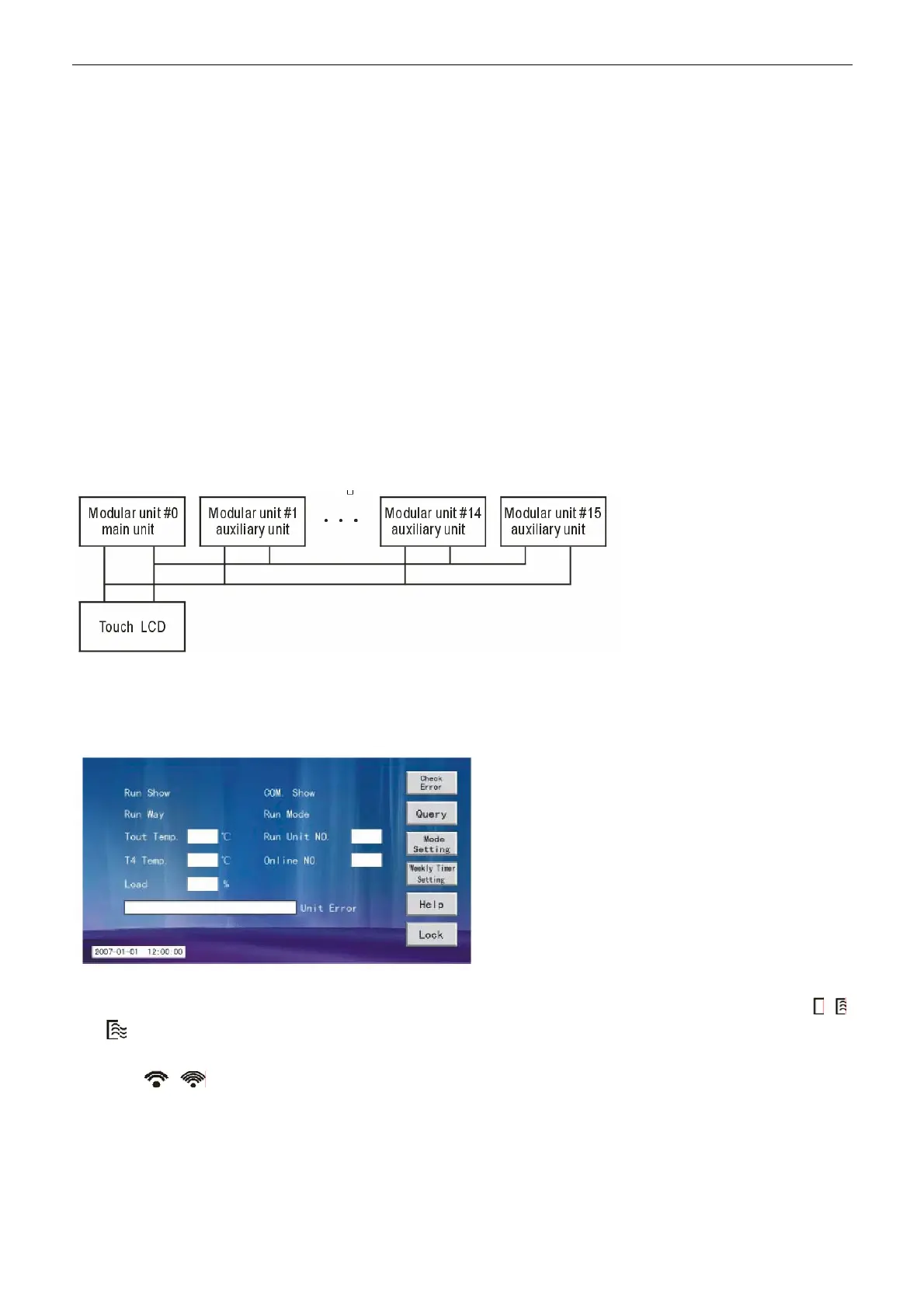
LCD operation window
The LCD Principal window as follows:
You could see the base information of the system in this principal window.
1) During operating, there are one or more modular units are in operating, dynamic circulation icons:
, ,
are displaying, while shutdown the system, nothing is displayed.
2) During communicating with main modular unit in normal occasion, dynamic circulation displays blank or
icons
, . In case main modular unit communication is blocked, nothing will be displayed.
3) ×During the system in controlled by upper PC system, “System control on” is displayed, otherwise,
nothing is displayed. (Reserve)
4) During the LCD screen in locking or LCD button in locking, “unlock” is displayed. While remove locking,
“Lock” is displayed.
 Loading...