16
18
FHL1 FHL2 FHLn
FCUnFCU2FCU1
T2 TnT1
11
10
12
1
32
6
7
8
9
12
4
26
If the volume of balance tank(9) is larger than 30L, the buffer tank(8) is unnecessary, otherwise the buffer tank(8)
should be installed and the total volume of balance tank and buffer tank should larger than 30L.The drain valve (6)
should be installed at the lowest position of the system. For the 5/7/9kW unit. The backup heater (1.5) is not integrated
in the outdoor unit. An independent backup heater can be selected and installed in the door. The wiring of the 3-way
valve (26) should follow the wiring of 2-way valve SV2 (refer to 9.6.6 Connection for other components/ For 2-way
valve SV2).
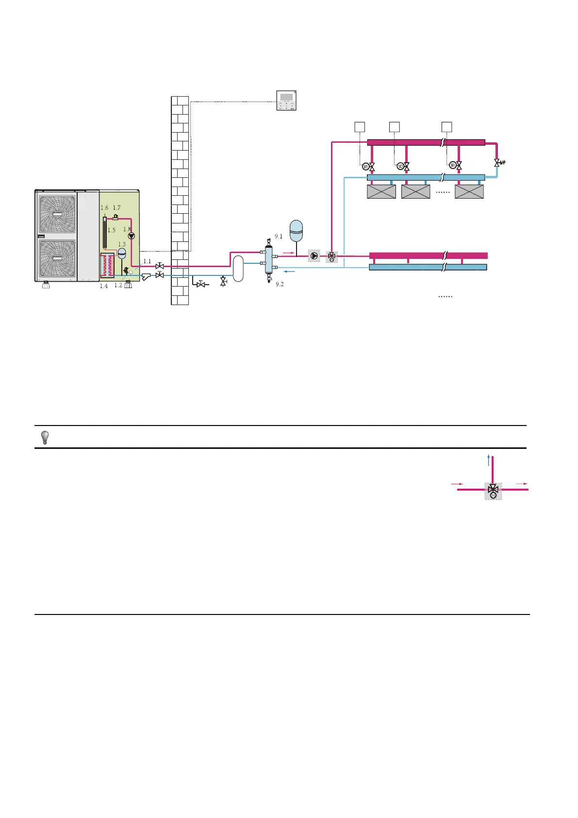
8.7 Application 7
Space cooling and heating application without a room thermostat connected to the unit, but the temperature sensor attached in the user
interface is used to control the ON/OFF of the unit. Heating is provided through floor heating loops. Cooling is provided through the fan coil
units. A 3-way valve is used to change the direction of water flow when the operation mode changed.
1 outdoor unit
1.1 manometer
1.2 pressure relif valve
1.3 expansion vessel
1.4 plate heat exchanger
1.5 backup heater
1.6 air purge valve
1.7 flow switch
1.8 P_i: circulate pump in the unit
2 y-shape filter
3 stop valve(field supply)
4 user interface
6 drain valve(field supply)
7 fill valve(field supply)
8 buffer tank(field supply)
9 balance tank(field supply)
9.1 air purge valve
9.2 drain valve
10 expansion vessel(field supply)
11 P_o:outside circulate
pump(field supply)
12 collector(field supply)
18 bypass valve(field supply)
26 3-way valve(field supply)
FHL 1...n floor heating loop
FCU 1...n fan coil units
M1...n motorized valve (field supply)
T1…n room thermostat (field supply)
NOTE
B
inlet
A
In normal condition, port A should be opened, while signal sent to the 3-way valve (26), port A will be closed and port B will be opened.
When in cool mode, ON signal will sent from outdoor unit to the 3-way valve (26), the cold water will flow through port inlet to port B, and
port B should connect to the fan coil units. While in heating mode, the hot water will flow through port inlet to port A, and port A should
connect to the floor heating loops. In this way, all the water from the unit will flow through the floor heating loops and thus ensure better
performance of the floor heating.
As the temperature sensor is used to detect the room temperature, the user interface (4) should be placed in the room where floor
heating loops and fan coil units is installed and away from the heating source. Correct configuration should be applied in the user
interface (refer to 10.7 field settings/TEMP. TYPE SETTING). The target room temperature can be set on the main page of user
interface, the target outlet water temperature will be calculated from climate related curves, the unit will turn off when the room
temperature reaches the target temperature.