EasyManua.ls Logo

Midea M-thermal Split MHA-V10W/D2N8 User Manual

Midea M-thermal Split MHA-V10W/D2N8
48 pages
To Next Page IconTo Next Page
Page #1 background imageLoading...
Page #1 background image
M-thermal Split
Outdoor Unit
INSTALLATION
AND OWNER’S MANUAL
Thank you very much for purchasing our product,
Before using your unit , please read this manual carefully and keep it for future reference.
IMPORTANT NOTE:
MHA-V4W/D2N8
MHA-V6W/D2N8
MHA-V8W/D2N8
MHA-V10W/D2N8
Question and Answer IconNeed help?

Do you have a question about the Midea M-thermal Split MHA-V10W/D2N8 and is the answer not in the manual?

Midea M-thermal Split MHA-V10W/D2N8 Specifications

General IconGeneral
BrandMidea
ModelM-thermal Split MHA-V10W/D2N8
CategoryHeat Pump
LanguageEnglish

Summary

Safety Precautions

Safety Symbol Meanings

Explains the meaning of DANGER, WARNING, CAUTION, and NOTE symbols used in the manual.

Unit Symbol Explanations

Details symbols displayed on the unit related to flammable refrigerant and manual references.

Important Information for the Refrigerant

Refrigerant Type and GWP

Specifies the refrigerant type (R32) and its Global Warming Potential (GWP).

Factory Charged Refrigerant Volume

Table detailing the factory-charged refrigerant volume in kg and CO2 equivalent for different models.

Installation Site

Selecting Location in Cold Climates

Prevent Sunshine

Installation Precautions

Install the Connecting Pipe

Refrigerant Piping Requirements

Details requirements for height difference, pipe length, and bends in refrigerant piping.

Leakage Detection

Leakage Testing Method

Describes using soap water or a detector to check for leaks at joints.

Heat Insulation

Connecting Method

Pipe Size Specifications

Provides pipe sizes (gas and liquid) for different models.

Connection Method Details

Explains the flaring connection method for both gas and liquid pipes.

Airtight Testing

Airtight Test Procedure

Details the process of charging nitrogen for airtight testing.

Air Purge with Vacuum Pump

Refrigerant Amount to be Added

Outdoor Unit Wiring

Safety Device Requirement

Wire Diameter Selection

Guides on selecting wire diameters based on rated current using provided tables.

Circuit Breaker Selection

Specifies requirements for circuit breakers, including contact separation and residual current devices.

Electronic Control Box

PCB B, Main Control Board

Test Running

Precautions on Refrigerant Leakage

Refrigerant Charge Limits

Details requirements for refrigerant charge limits in unventilated areas based on room size.

Defrost in the Heating Operation

Error Codes

Temperature Sensor Errors (ES, E6, E9, ER)

Details causes and corrections for errors related to condenser, ambient, suction, and discharge temperature sensors.

Communication Error (Main Control Board B to Hydraulic Module)

H0 Error Cause and Correction

Explains causes like loose wiring or interference and suggests corrective actions for H0 error.

Communication Error (Inverter Module PCB A to Main Control Board PCB B)

H1 Error Cause and Correction

Lists causes like power issues or loose connections and suggests corrective actions for H1 error.

Three Times P6 Protect

DC Fan Failure

Main Circuit Voltage Failure

Pressure Sensor Failure

Main Control Board PCB B EEprom Failure

H6 Displayed 10 Times in 2 Hours

Low Pressure Protection (HP)

Low Pressure Protection (P0)

P0 Error Cause and Correction

Details causes like low refrigerant, dirty heat exchanger, or valve issues and their corrective actions.

High Pressure Protection (P1)

P1 Error Cause and Correction

Explains causes like low water flow or overcharging refrigerant and their corrective actions.

Compressor Overcurrent Protection (P3)

P3 Error Cause and Correction

States reasons similar to P1 and low voltage, suggesting corrective actions.

High Discharge Temperature Protection (P4)

P4 Error Cause and Correction

Lists sensor connection issues and suggests corrective actions for P4 error.

Module Protection (P6)

P6 Error Cause and Correction

Details causes like narrow space, dirty heat exchanger, or loose wires and their corrective actions.

DC Fan Motor Protect (P9)

High Temperature Protection of Condenser Outlet

Transducer Module Temperature Too High Protect (E7)

DC Generatrix Voltage Too Low (F1)

F1 Error Cause and Correction

Details causes related to power supply, main board, or inverter board and suggests corrective actions.
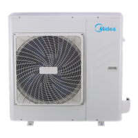
Technical Specifications

Annex B: Electrically Controlled Wiring Diagram

Related product manuals