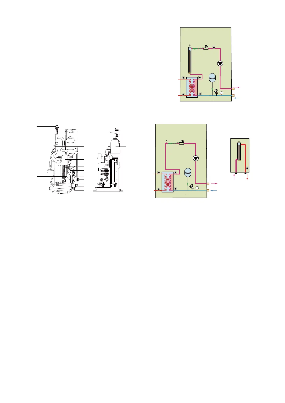
9.Flow switch
The flow switch checks the flow in the water circuit and protects
the
heat exchanger against freezing and the pump against damage.
10.Pump
The pump circulates the water in the water circuit.
11.Heat exchanger
The manometer provides a water pressure readout of the water
circuit.
12.Water outlet connection
12.1 Air purge valve
13.Pressure relief valve
The pressure relief valve prevents excessive water pressure in
the water circuit by opening at 43.5 psi (3 bar) and discharges
water.
14.Water inlet connection
14.1 Drain valve
15.Electrical heating tape(15.1-15.3)
9.2.2 Functional diagram of hydraulic compartment
1 Air purge valve
2 Backup heater vessel with backup heater
3 Expansion vessel
5 Refrigerant gas connection
7 Refrigerant liquid connection
8 Manometer
9 Flow switch
10 Circulation Pump
11 Heat exchanger
12 Water outlet connection
13 Pressure relief valve
14 Water inlet connection
15.1 Electrical heating tape
15.2 Electrical heating tape
15.3 Electrical heating tape
16 Water inlet connection
17 Water outlet connection
Temperature sensors:TW_in;TW_out;T2B;T2;T1
1.Air purge valve
Remaining air in the water circuit will be automatically removed via
the air purge valve.
4.Pressure Sensor
7.Refrigerant liquid connection
6.Temperature sensors
Four temperature sensors determine the water and refrigerant
temperatures at various points in the water circuit.
9.Flow switch
The flow switch checks the flow in the water circuit and protects the
heat exchanger against freezing and the pump against damage.
10.Pump
The pump circulates the water in the water circuit.
8.Manometer
13.Pressure relief valve
The pressure relief valve prevents excessive water pressure in
the water circuit by opening at 43.5 psi (3 bar) and discharging
water.
14.Water inlet connection
19
3
1
4
7
18
6
9
10
11
8
15.1
12
12.1
13
14
14.1
1-phase 10~16kW
3-phase 12~16kW
1
2
3
5
7
T2B
T2
TW_in
TW_out
9
T1
10
12
14
813
11
15.1
15.2
15.3
1
3
5
7
T2B
T2
TW_in
TW_out
9
10
12
14
813
11
15.1
15.2
15.3
1-phase 5/7/9kW
1-phase 5/7/9kW
2
T1
16 17
backup heater box
(optional)
3.Expansion vessel (0.88gallons (2 L))
The manometer provides a water pressure readout of the water
circuit.
15.1.Electrical heating tape
18. sleeve for insert temperature sensor
12.Water outlet connection
11.Heat exchanger
12.1 Air purge valve
14.1 Drain valve
NOTE:for 5/7/9 kW unit,If backup heater box is installed, the port
(CN6) for T1 in the main control board of hydraulic should connect
to the corresponding port in the backup heater box(please refer to
the Installation & Owner’s Manual of backup heater box).
if backup heater box is not installed, the T1 sensor should insert into
the sleeve which near the pump(10) and connect to the port CN6.