M thermal Mono
76 200204
Midea M thermal Mono Service Manual
Procedure
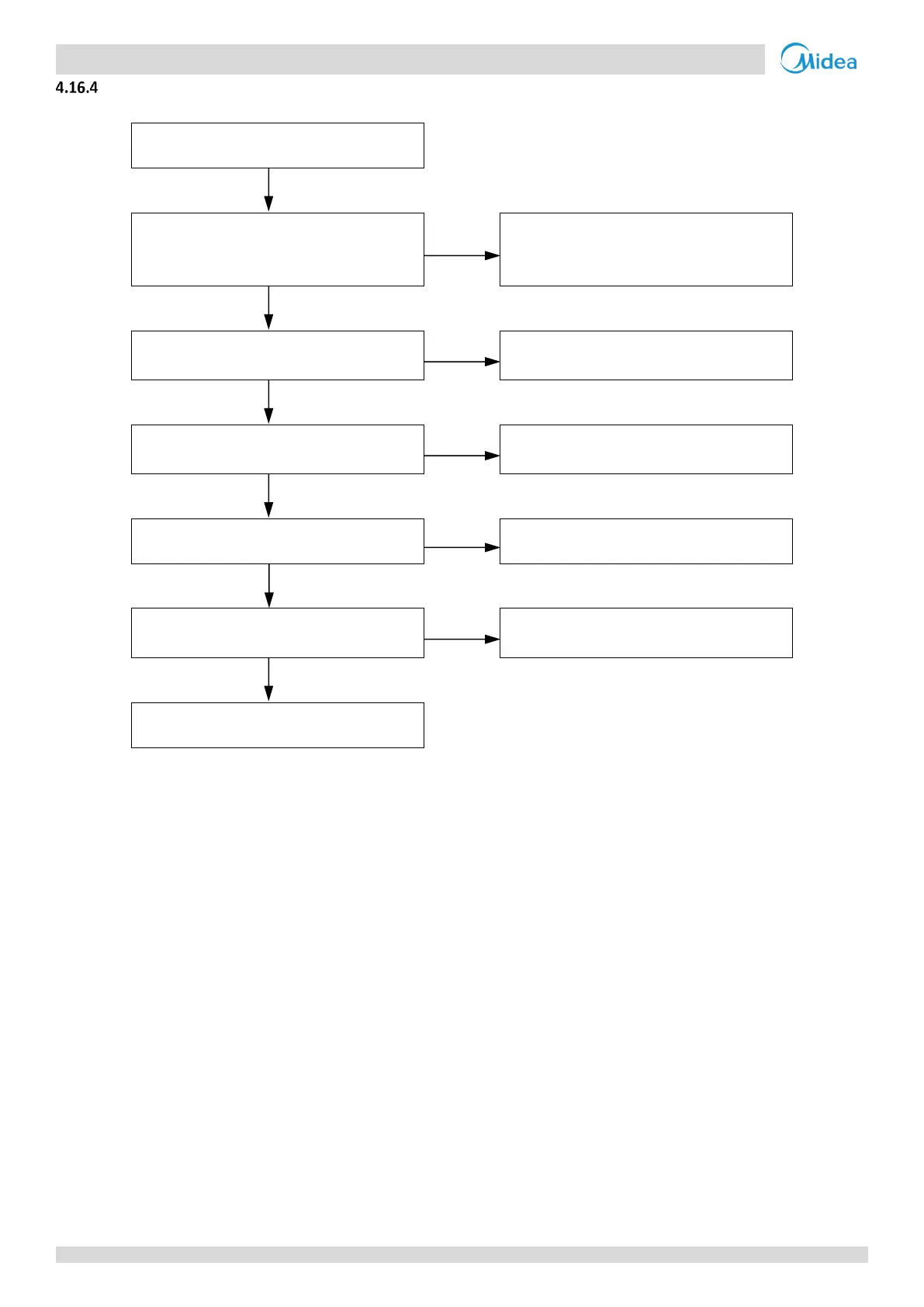
High pressure switch connection or
pressure sensor connection on
refrigerant system main PCB is loose
1
Ensure the pressure switch is connected
properly
Pressure sensor has short-circuited or
failed
2
Replace the pressure sensor
The high pressure side is blocked, caused
by crushed or bent pipe or blocked EXV
3
Inspect the system and fix the error
The heat exchange is poor
4
Inspect the system and fix the error
The water flow rate is not sufficient in
cooling mode
5
Inspect the water system and fix the
error
Notes:
1. High pressure switch connection is port CN13 on the MHA-V4(6,8,10)W/D2N8-B outdoor unit refrigerant system main PCB (labeled 16 in Figure 4-2.2 in
Part4, 2.3 "Main PCB for Refrigerant System, Inverter Module"). port CN13 on the MHA-V12(14,16)W/D2N8-B outdoor unit refrigerant system main PCB
(labeled 16 in Figure 4-2.3 in Part 4, 2. 3 "Main PCB for Refrigerant System, Inverter Module"), port CN31 on the MHA-V12(14,16)W/D2RN8-B outdoor unit
refrigerant system main PCB (labeled 20 in Figure 4-2.4 in Part 4, 2. 3 "Main PCB for Refrigerant System, Inverter Module").
2. Measure the resistance among the three terminals of the pressure sensor. If the resistance is of the order of mega Ohms or infinite, the pressure sensor
has failed.
3. High pressure side blockage causes discharge temperature to be higher than normal, discharge pressure to be higher than normal and suction pressure to
be lower than normal.
4. In heating mode check water side heat exchanger, water piping, circulator pumps and water flow switch for dirt/blockages. In cooling mode check air side
heat exchanger, fan(s) and air outlets for dirt/blockages.
5. Check water pressure on the manometer. If the water pressure is not > 1 bar, water flow is insufficient. Refer to Figure 2-1.2 and 2-1.6 in Part 2, 1 “Layout
of Functional Components”.
 Loading...