25
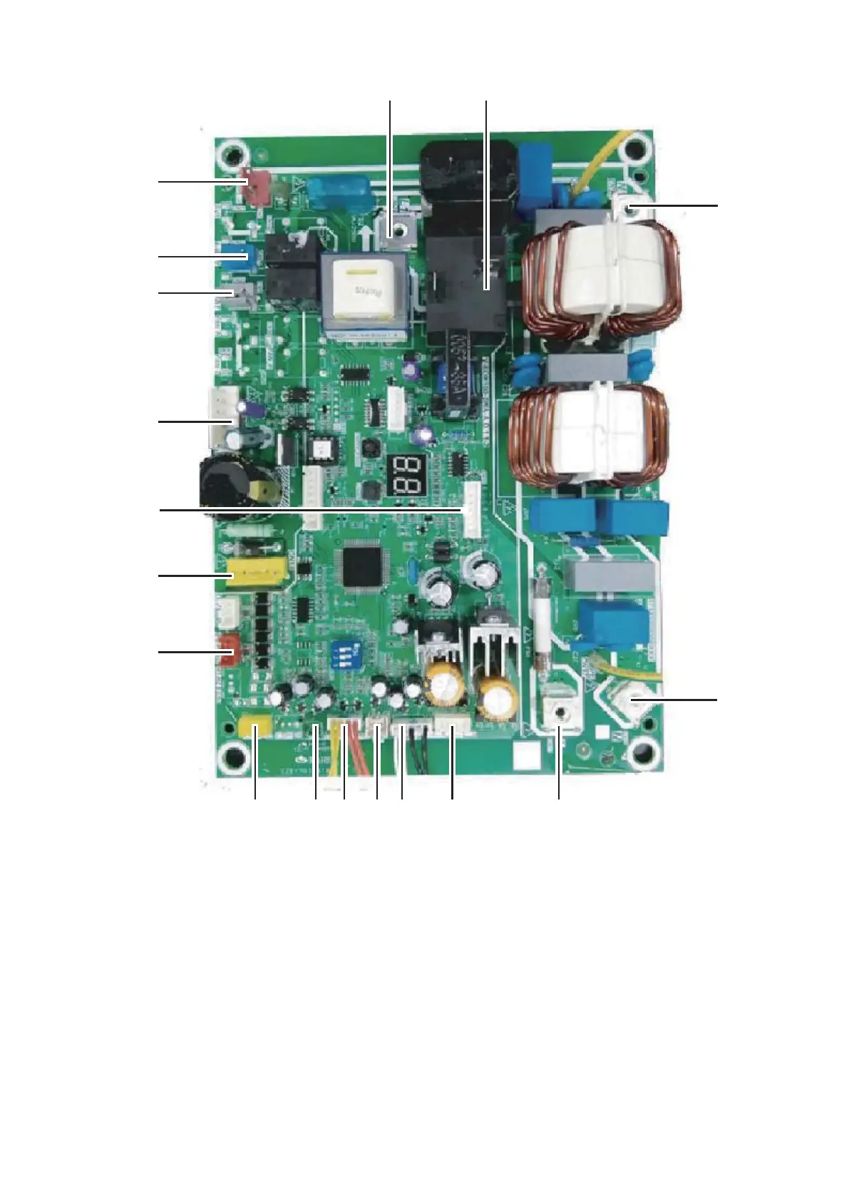
1 Rectifier bridge input port L
2 Hydraulic compartment input port2
3 Rectifier bridge input port N
4 Power supply N
5 Power supply L
6 Transformer output port
7 BLACK: T3 temperature sensor port
WHITE:T4 temperature sensor port
8 TP temperature sensor port
9 YELLOW: High pressure switch
RED: Low pressure switch
10 Th temperature sensor port
11 Pressure sensor port
12 Port for communication between this PCB and main control
board of hydraulic module
13 P/N/+18V port
14 To IPDU/PFC
15 DC fan port
16 Compression electromechanical heating belt
17 4-way valve port
18 Transformer input port
1-phase 5/7/9kW
PCB A
2
4
567891011
12
13
15
14
16
17
18
3
1
PCB B, Main control board for 1 phase 5/7/9 kW unit.