M thermal Mono
202004 95
Situation 3: L0 error appears within 2 seconds of compressor start-up
U V W wire between inverter module and
compressor is not connected properly
1
Ensure U V W wire is connected properly
Communication port for connection to
inverter module on refrigerant system
main PCB is damaged
2
Replace the inverter module
3
Notes:
1. Connect the U V W wire from the inverter module to the correct compressor terminals, as indicated by the labels on the compressor.
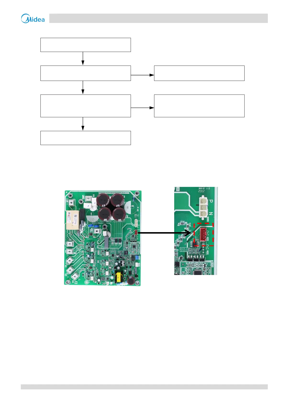
2. Measure the voltage between each of W-, W+, V-, V+, U-, U+ and GND when the unit is in standby. The normal voltage should be 2.5V-4V and the six
voltages should be same, otherwise the communication terminal has failed. Refer to Figure4-4.8.
Figure 4-4.8: Connection port for inverter module
3. When replacing an inverter module, a layer of thermally conductive silica gel should be painted on the IPM module (on the reverse side of the inverter
module PCB). Refer to Figure 4-4.2.
 Loading...