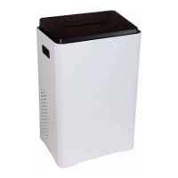
Do you have a question about the Midea MPN-08CRN1-BH9 and is the answer not in the manual?
Guidelines for electrical work, self-repair, sharp edges, installation area, power cable, flammable gas, strange sounds, water damage, cleaning, and long-term storage.
Checks for refrigerant leakage, drain hose, product level, noise, lifting, and sea wind exposure.
Precautions for skin exposure, special uses, airflow, cleaning, sharp parts, stepping, filter, battery handling, and draining water.
Selects operating modes (AUTO, COOL, DRY, FAN, HEAT) and indicates the selected mode.
Initiates AUTO ON/OFF timer programs in conjunction with UP/DOWN buttons.
Controls the power switch of the unit.
Initiates the SLEEP operation mode.
Controls fan speed (LOW, MED, HI) and indicates the selected speed.
Activates the ion generator to remove airborne particles.
Adjusts temperature and timer settings, with Celsius/Fahrenheit conversion.
Shows temperature, auto-timer, and room temp. Includes error codes (E1, E2, P1).
Controls louver angle, allowing stopping or auto swing.
Specifies placement for optimal air outlet flow, minimum clearance from obstacles, and prohibition of use in washrooms.
Details how to prepare and connect the exhaust hose to the unit.
Attaching foam seal to the window stool for sealing purposes.
Adjusting and securing the window panel to the window stool with screws.
Applying foam seal to the top of the window for proper sealing.
Ensuring the window sash is closed firmly against the installed window panel.
Sealing the gap between the window sashes with foam seal.
Applying foam seal to the window frame for sealing.
Adjusting and securing the sliding window panel to the window stool with screws.
Applying foam seal to the top of the window for sealing.
Ensuring the sliding sash is closed firmly against the installed window panel.
Sealing the gap between the sliding window sashes with foam seal.
Procedure to test compressor continuity using an ohmmeter for open windings.
Testing for grounding of the compressor by checking resistance between terminals and the compressor body.
Diagnosing compressor inefficiency due to faulty valves by checking system pressures and temperature differences.
Explanation of external overload protection and its function based on amperage and temperature.
Testing the continuity of an external overload protector.
Description of internal overload protection embedded in motor windings.
Testing continuity of internal overload protectors.
Details on performing repairs in the sealed refrigeration circuit.
Lists necessary equipment for refrigerant system repairs, including meters, recovery systems, pumps, and gauges.
Specifies capabilities required for repair equipment, such as CFC recovery, evacuation, and charging.
Detailed steps for replacing a hermetic compressor, including refrigerant recovery, flushing, and leak testing.
Steps for handling compressor motor burnout, including refrigerant recovery, flushing, and reassembly.
Troubleshooting and service for rotary compressors, focusing on mounts and terminal identification.
Procedures for accurately charging refrigerant, including methods for high and low side introduction.
Steps to test the fan motor's functionality and speed settings using a test cord.
Procedures for testing the capacitor's functionality.
Explains the role of the capacitor and provides a test procedure using an ohmmeter for compressor and fan motors.
Troubleshoots issues related to the unit's display and buttons, covering power failure and transformer issues.
Addresses remote control malfunctions, including battery checks and display board/main PCB issues.
Diagnoses intermittent fan motor operation, involving capacitor checks and bearing issues.
Identifies causes for compressor stopping immediately after startup, such as refrigerant issues or internal blockage.
Troubleshoots scenarios where the fan motor fails to operate, checking power, wiring, and PCB.
Addresses fan motor noise issues, including scroll rubbing, loose screws, worn bearings, and internal motor noise.
Diagnoses why the compressor doesn't run when the fan motor is operational, checking voltage, wiring, and PCB.
Troubleshoots excessive noise from the unit, including copper tubing, water level alarms, and motor issues.
Explains the water full alarm condition and its resolution, involving water depth sensors.
Identifies reasons for poor cooling/heating performance, such as air filters, discharge pipes, or unit sizing.
Assesses if the unit is properly sized for the intended area for effective cooling or heating.
Diagnoses failure of shaded pole motors in the condenser and evaporator.
Checks fan motor capacitor and removes airflow obstructions.
Addresses airflow issues by cleaning or removing obstructions from inlets/outlets.
Explains how to check for refrigerant leaks, recycle refrigerant, and recharge the system.
Discusses capillary tube issues like blockage or leaks affecting refrigerant flow.
Diagnoses compressor problems like damaged valves or issues affecting pressure regulation.
Suggests reducing excessive heat sources to improve unit performance.
Checks voltage and terminals for power supply issues.
Inspects and corrects loose or incorrect wiring connections.
Advises checking and adjusting temperature settings for optimal performance.
Recommends checking and adjusting the operating mode for desired function.
Checks compressor, overload protector, or wiring for faults.
Checks and replaces a damaged electric heater.
Checks and replaces an overheating fuse.
Checks PCB voltage and replaces if unit fails in heating mode.
Checks power supply voltage and calls an electrician if it's too low.
Checks the main PCB for a shorted or damaged compressor relay.
Addresses compressor protection due to excessively high room temperature.
| Brand | Midea |
|---|---|
| Model | MPN-08CRN1-BH9 |
| Category | Air Conditioner |
| Language | English |


 Loading...