Do you have a question about the Midea MSMBBU-12HRFN1-QRD0GW and is the answer not in the manual?
Essential safety guidelines to prevent injury and property damage during operation and service.
Critical warnings about electrical hazards, improper installation, and potential risks during use.
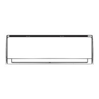
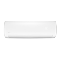
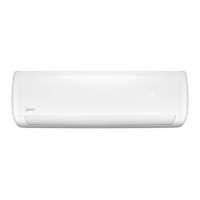
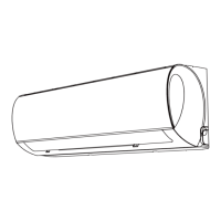
Provides detailed dimensions and diagrams for the indoor unit of the air conditioner.
Provides detailed dimensions and diagrams for the outdoor unit of the air conditioner.
Specifies torque values for various pipe diameters during installation to ensure proper connections.
Guidelines for selecting appropriate power cord cross-sectional areas based on appliance current rating.
Details pipe size, standard length, maximum elevation, and refrigerant amount for different models.
Procedures for initial system installation, including leak testing and evacuation.
Instructions for adding refrigerant to systems that have been in use for many years.
Steps for collecting refrigerant and purging air during re-installation after indoor unit repair.
Procedures for system evacuation and refrigerant charging during re-installation after outdoor unit repair.
Defines technical abbreviations used for sensors and system parameters within the manual.
Explains the meaning of various icons and digital displays on the indoor unit's display board.
Details various protection mechanisms for the compressor, fan, and electronic modules.
Describes different operating modes like cooling, heating, auto, and defrosting with their rules.
Lists error codes displayed on the indoor unit and their corresponding LED status.
Diagnosis and solution for EEPROM parameter errors (E0/F4) involving PCB issues.
Diagnosis and solution for indoor/outdoor unit communication errors (E1) related to wiring or PCBs.
Diagnosis and solution for fan speed control issues (E3/F5) like motor faults or wiring mistakes.
Diagnosis and solution for refrigerant leakage detection errors (EC) involving sensors or system problems.
Diagnosis and solution for temperature sensor circuit errors (E4/E5/F1/F2/F3) like wiring or faulty sensors.
Diagnosis and solution for IPM malfunction or over-current protection errors (P0).
Diagnosis and solution for over/under voltage protection errors (P1) related to power supply or PCBs.
Diagnosis and solution for compressor top temperature protection errors (P2) due to airflow or power issues.
Diagnosis and solution for inverter compressor drive errors (P4) involving communication or IPM faults.
Procedure to measure the resistance of temperature sensors using a tester for diagnosis.
Method to check compressor winding resistance values using a tester for diagnosis.
| Cooling Capacity | 12000 BTU/h |
|---|---|
| Refrigerant | R410A |
| Power Supply | 220-240V, 50Hz |
| Energy Efficiency Ratio (EER) | 3.21 |
| Dimensions (Indoor Unit) | 805 x 194 x 285 mm |
| Type | Split Air Conditioner |