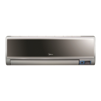
Do you have a question about the Midea MSV1-07CRN1 and is the answer not in the manual?
Lists the specific Midea air conditioner models this service manual applies to.
Essential safety guidelines to prevent injury and property damage during installation and servicing.
Critical warnings regarding electrical safety, grounding, and proper installation procedures.
Important cautionary notes for safe operation and maintenance to prevent damage or hazards.
Recommendations for proper usage and handling during the air conditioner's operation.
Details the various operational modes and features of the indoor air conditioning unit.
Outlines the operational aspects and components of the outdoor air conditioning unit.
Provides the physical dimensions (W, H, D) for the indoor air conditioner unit.
Provides the physical dimensions (W, H, D, L1, L2) for the outdoor air conditioner unit.
Illustrates the refrigerant flow path during the cooling operation cycle.
Depicts the refrigerant circulation for the heat pump mode, including key valves.
Defines the acceptable ambient and indoor temperature ranges for effective cooling operation.
Specifies the temperature ranges for optimal performance during heating operation.
Shows the electrical connections for the indoor unit, including components and terminals.
Details the electrical connections for the outdoor unit, highlighting key components and wiring.
Lists the required torque values for various pipe fitting sizes during installation.
Provides guidelines for selecting and connecting the power cord based on current capacity.
Specifies maximum pipe lengths and elevation differences for optimal refrigerant performance.
Explains the process of removing air and moisture from the refrigeration piping.
Details the steps for recovering refrigerant during re-installation or maintenance.
Outlines the method for purging air after refrigerant has been removed or the system opened.
Describes how to balance the refrigerant charge using the 2-way and 3-way valves.
Explains how to create a vacuum in the refrigerant system to remove non-condensable gases.
Details the steps for charging the system with the correct amount of refrigerant.
Specifies the operating voltage, frequency, and ambient conditions for the electronic control system.
Defines the various symbols and abbreviations used to describe sensor readings and protection codes.
Lists and briefly describes the various operational functions of the air conditioner.
Explains the built-in protection features that safeguard the compressor and unit operation.
Describes the operation when only the fan is active, without cooling or heating.
Details the control logic for the cooling mode, including fan speed and compressor engagement.
Explains the operation and fan speed setting for the dehumidification mode.
Describes the control logic and fan actions during heating operation, including anti-cold wind.
Details the conditions and actions for the defrosting mode, available during heating.
Explains how the unit automatically selects cooling, heating, or fan mode based on temperature.
Describes how to manually activate a forced cooling mode for rapid temperature adjustment.
Explains the sleep function that adjusts temperature and fan speed for comfort and energy saving.
Describes the unit's ability to resume previous settings after a power interruption.
Details the air purification function controlled via the remote controller.
Explains the meaning and function of various indicators shown on the LCD display board.
Lists the error codes displayed on the indoor unit and their corresponding status or causes.
Provides a step-by-step guide for diagnosing operational issues when the unit is not responding.
Guides troubleshooting for intermittent resetting issues, often related to voltage or PCB faults.
Diagnoses issues when the operation lamp flashes and the timer lamp is off.
Diagnoses issues when the operation lamp flashes and the timer lamp is on.
Diagnoses issues when the operation lamp is off and the timer lamp flashes.
Addresses scenarios where lamps are on or flashing, indicating EEPROM errors or over-zero signal detection faults.
| Cooling Capacity | 7000 BTU/h |
|---|---|
| Refrigerant | R410A |
| Power Supply | 220-240V, 50Hz |
| Air Flow (High) | 450 m³/h |
| Weight | 8.5 kg |
| Type | Split |
| EER | 3.21 |


