Do you have a question about the Midea MSV1-12HRDN1-QC2 and is the answer not in the manual?
| Brand | Midea |
|---|---|
| Model | MSV1-12HRDN1-QC2 |
| Category | Air Conditioner |
| Language | English |
General safety instructions to prevent injury and property damage during operation and installation.
Specific warnings related to installation, electrical safety, and operational hazards like fire or shock.
Cautionary advice for installation and operation to prevent product failure or damage.
Guidelines for safe and proper operation, including avoiding direct exposure to cool air and proper cleaning.
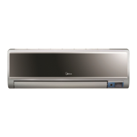
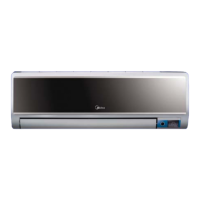
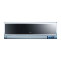
Overview of indoor unit functions like remote control, temperature sensing, fan control, and airflow direction.
Lists functions such as lonizer, Self-clean, Follow me, Tele Remote, Self-diag, Anti-cold, Auto defrost.
Overview of outdoor unit features like power relay control, low noise system, hydrophilic fin, 4-way valve.
Dimensional drawings and measurements for the indoor unit models MSV1-09HRDN1-QC2(A) and MSV1-12HRDN1-QC2(A).
Dimensional drawings and measurements for the outdoor unit models MOC-09HDN1-QC2 and MOC-12HDN1-QC2.
Wiring diagram detailing electrical connections within the indoor unit, including PCB, sensors, and motors.
Wiring diagram showing electrical connections for the outdoor unit, including compressor, fans, sensors, and heaters.
Table specifying torque values for tightening flare nuts based on pipe diameter.
Guidance on selecting the correct power cord size based on unit grade (9K/12K).
Specifications for standard pipe length, maximum elevation, and additional refrigerant.
Procedure and required tools for purging air from the refrigeration piping system during installation.
Procedure for pumping down the refrigerant during re-installation or removal.
Procedure for re-purging air from the system after it has been pumped down.
Procedure for balancing refrigerant levels by adjusting 2-way and 3-way valves.
Procedure for creating a vacuum in the refrigeration system using a vacuum pump.
Procedure for charging the system with the correct amount of refrigerant.
Performance graphs showing cooling and heating characteristics based on outdoor temperature and piping length.
Performance graphs illustrating cooling and heating characteristics for the 12K model based on ambient conditions.
List of abbreviations used for temperature sensors (T1, T2, T3, T4) and their meanings.
Explanation of icons and indicators on the indoor display board, detailing their meaning during operation.
Details on various protection functions like compressor delay, temperature protection, and sensor failures.
Description of the Fan-Only mode, including temperature setting and louver actions.
Explanation of compressor operation, anti-freezing, and current control within the cooling mode.
Details on the drying mode, including fan speed, temperature protection, and louver action.
Explanation of indoor fan action, anti-cold-wind function, and auto fan control in heating mode.
Specific high temperature protection for the indoor heat exchanger in heating mode.
Conditions for initiating and ending the defrosting cycle in heating mode.
Diagram illustrating timing and actions of compressor, 4-way valve, and fans during defrosting.
How the unit automatically selects cooling, heating, or fan-only based on temperature difference.
Details on forced auto and forced cooling modes, activated via touch buttons.
Describes the operation of the 4-way valve in different modes (cooling, heating, drying, etc.).
Information on the outdoor fan's starting and stopping behavior in different operating modes.
Details on setting the timer for automatic ON/OFF operations with specified resolution and tolerance.
Explanation of the sleep mode's operation, including temperature adjustments and duration.
How the unit restores previous settings after a power failure.
Describes the automatic opening and closing of the front panel upon power on/off.
Details on the Clean Air function, its activation, and dependency on the indoor fan.
How to activate and operate the self-cleaning function, including its sequence and limitations.
Explanation of the "Follow me" feature, where the unit tracks temperature from the remote.
Details on the optional heating cable for deicing and its thermostat control.
Important safety warning regarding discharging stored electricity in capacitors before servicing.
Table listing error codes (E0-E6, P0-P4) displayed on the indoor unit and their meanings.
Flowcharts and procedures for diagnosing and resolving specific error codes like E0, E1, E2.
Procedure for checking compressor windings resistance using a multi-meter.
Procedure for measuring the resistance of outdoor fan motor windings.
Procedure for measuring the resistance of indoor fan motor windings.
Procedure for checking the resistance of the step motor windings.
Guidance on measuring resistance of temperature sensors and reference R-T data.