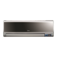
Do you have a question about the Midea MSV1-12HRDN1 and is the answer not in the manual?
Safety instructions to prevent injury and property damage during operation and installation.
Critical warnings regarding electrical shock, fire hazards, and improper installation or usage.
Visual representation of the electronic circuits and components for the unit's operation.
Electrical connection diagram illustrating the wiring layout for indoor and outdoor units.
Specifies required torque values for tightening various fittings during installation.
Guidelines for selecting and connecting power cords based on unit capacity.
Details on maximum pipe length, elevation limits, and additional refrigerant for different capacities.
Procedure for removing air and moisture from the refrigeration system before operation.
Steps to recover refrigerant into the outdoor unit for unit removal or re-installation.
Procedure for purging air from the system after re-installation and before charging refrigerant.
Instructions for balancing refrigerant levels using the system's valves.
Process of removing air and moisture from the refrigerant circuit using a vacuum pump.
Procedure for charging the system with the correct amount of refrigerant.
Refrigerant pressure data for the MSV1-09HRDN1 model under various operating conditions.
Refrigerant pressure data for the MSV1-12HRDN1 model under various operating conditions.
Cooling and heating capacity data for the MSV1-09HRDN1 model at different temperatures.
Cooling and heating capacity data for the MSV1-12HRDN1 model at different temperatures.
Explanation of the various indicators and symbols displayed on the unit's display board.
Details on internal protection mechanisms that prevent damage or ensure safe operation.
Description of the fan-only operating mode and available fan speeds.
Explanation of how the unit operates in cooling mode, including valve actions and fan control.
Description of the dehumidifying mode, its characteristics, and protection features.
Explanation of how the unit operates in heating mode, including valve actions and fan control.
Details on the automatic defrosting cycle for heating mode, including conditions and actions.
Optional function to protect the unit when outdoor temperatures are very low.
How the unit automatically selects between cooling, heating, or fan-only modes.
Describes how to change operating modes using the manual switch on the unit.
Details on setting and operating the unit's timer functions for on/off scheduling.
Function to adjust temperature and fan speed automatically for comfortable sleep.
Automatically restores previous settings after a power interruption.
Enables high-speed fan operation and increased compressor frequency for rapid cooling/heating.
Lists error codes displayed on the indoor unit and their corresponding LED status for diagnostics.
Flowchart to diagnose issues when the unit is unresponsive or has no indicators lit.
Addresses issues where the unit frequently resets during operation due to low chip voltage.
Troubleshooting steps for when operation and timer lamps flash with both lamps off.
Troubleshooting steps for when operation lamp flashes and timer lamp is on.
Troubleshooting steps for when operation lamp is off and timer lamp flashes.
Troubleshooting steps for EEROM errors or defective indoor PCB.
Identifies alarm for main chip failure to detect over-zero signal, indicating main control board fault.
| Brand | Midea |
|---|---|
| Model | MSV1-12HRDN1 |
| Category | Air Conditioner |
| Language | English |

