29
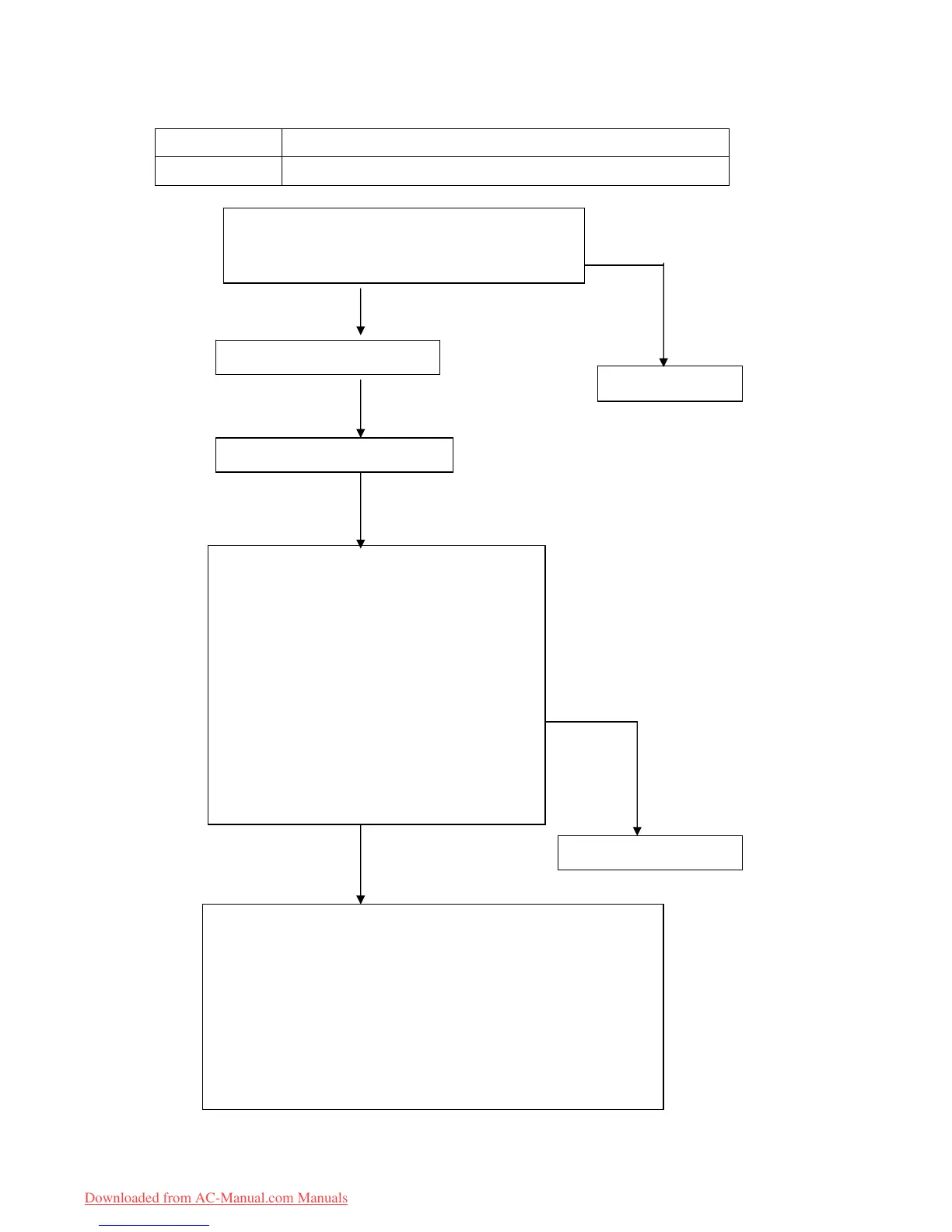
Display LED STATUS
P4 Inverter module protection
Check the connectors CN12, CN7, CN1 in outdoor PCBs
Is connection to connector good?
Are the wires to compressor right?
Check the outdoor inverter module.
Is it breakdown between P-N,P-U,P-V;N-W,N-U,N-V
At inverter module
Normally,
P-N: ~1.0MΏ
P-U: ~2.0MΏ
P-V: ~2.0MΏ
P-W: ~2.0MΏ
N-W: ~1.0MΏ
N-U: ~1.0MΏ
N-V: ~1.0MΏ
Check compressor
1.Turn on the unit in cooling or heating in different season, use a frequency
meter to test the frequency in one of the three wires to compressor, if there
is frequency in wires, but compressor do not run, the compressor is
defective.
2.Between U,V,W three terminals , the resistance is about 0.6 Ώ.
Inverter module is defective
Repair connector
Yes No
Yes
Yes
No
Downloaded from AC-Manual.com Manuals
 Loading...