EasyManua.ls Logo

Midea MSY-12HRDN1-QC4 User Manual

Midea MSY-12HRDN1-QC4
44 pages
To Next Page IconTo Next Page
Page #1 background imageLoading...
Page #1 background image
Website: www.mideaaircon.com
Service Manual
AIR CONDITIONER
DC Inverter
Split Wall-Mounted Type
Model Refrigerant type Power supply
MSY-09HRDN1-QC8 R410A 1Ph, 220~240V, 50Hz
MSY-12HRDN1-QC4 R410A 1Ph, 220~240V, 50Hz
MSY-09HRDN1-QC2 R410A 1Ph, 220~240V, 50Hz
MSY-12HRDN1-QC2 R410A 1Ph, 220~240V, 50Hz
MSY
-18HRDN1-QC2 R410A 1Ph, 220~240V, 50Hz
Y series
Question and Answer IconNeed help?

Do you have a question about the Midea MSY-12HRDN1-QC4 and is the answer not in the manual?

Midea MSY-12HRDN1-QC4 Specifications

General IconGeneral
Power Supply220-240V, 50Hz
RefrigerantR410A
Dimensions (Indoor Unit)805x194x285 mm
Dimensions (Outdoor Unit)720x270x495 mm
TypeSplit
Cooling Capacity12000 BTU
Noise Level (Indoor)39 dB(A)

Summary

1. Precaution

1.1 Safety Precaution

Instructions to prevent injury to users, people, and property damage.

1.2 Warning

Warnings related to installation, operation, and maintenance of the unit.

2. Function

Indoor unit

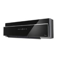
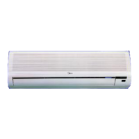
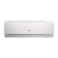
Describes the functions and features related to the indoor unit.

3. Dimension

3.1 Indoor Unit

Provides dimensional specifications for the indoor unit models.

4. Specification

MSY-09HRDN1-QC8, MSY-12HRDN1-QC4

Detailed specifications for specific Midea air conditioner models.

5. Refrigerant cycle diagram

6. Wiring diagram

6.1 Indoor Unit

Wiring diagram for indoor units of various Midea models.

7. Installation details

7.1 Wrench torque sheet for installation

Specifies torque values for wrench tightening during installation.

7.2 Connecting the cables

Guidance on selecting the correct power cord for connections.

7.3 Pipe length and the elevation

Details on pipe length and elevation limits for installation.

7.4 Air purging of the piping and indoor unit

Procedure and tools required for air purging the refrigeration system.

7.5 Pumping down (Re-installation)

7.6 Re-air purging (Re-installation)

7.7 Balance refrigerant of the 2-way, 3-way valves

7.8 Evacuation

7.9 Gas charging

8. Electronic function

8.1 Abbreviation

List of abbreviations used for sensor temperatures.

8.2 Display function

Explanation of icons displayed on the indoor unit.

8.3 Protection

8.4 Fan-Only Mode

Description of the Fan-Only operating mode.

8.5 Cooling Mode

8.6 Drying mode

8.7 Heating mode

Details on indoor fan action and anti-cold-wind function in heating.

8.8 Auto mode function

8.9 Forced operation function

8.10 Action of 4-way valve

8.11 Two speeds outdoor fan function

8.12 Timer function

8.13 Sleep function mode

8.14 Auto-Restart function

8.15 Super Ionizer function

8.16 Self-clean function

8.17 Follow me function

8.18 Outdoor heating cable (Optional)

9. Troubleshooting

Safety

Safety precautions, especially regarding capacitors and electrical discharge.

9.1 Indoor Unit Error Display

9.2 Diagnosis and Solution

9.3 Checking for temperature sensors

Related product manuals