Do you have a question about the Midea MSY-18HRDN1-QC2 and is the answer not in the manual?
Essential safety guidelines for users and technicians to prevent injury and equipment damage.
Critical warnings related to electrical hazards, installation, and product operation to avoid severe risks.
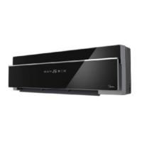
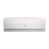
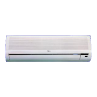
Details various operational modes and features of the indoor unit, including fan speeds and air direction control.
Explains the operational features of the outdoor unit, such as noise reduction, fin properties, and valve controls.
Provides the specific width, height, and depth measurements for different indoor unit models.
Lists the physical dimensions for various outdoor unit models, essential for installation planning.
Details electrical, performance, and physical specifications for indoor units, including capacity and power ratings.
Continues specification details for indoor units, covering compressor, fan motor, and refrigerant oil.
Provides key specifications for outdoor units, including power supply, cooling/heating capacity, and refrigerant piping.
Further details on outdoor unit specifications, such as dimensions, noise levels, and connection wiring types.
Visual representation of the refrigerant path through the system, showing key components like compressor and heat exchangers.
Illustrates the electrical connections within the indoor unit, showing components and their wiring.
Provides wiring schematics for different outdoor unit models, detailing component connections.
Specifies the correct torque values for tightening fittings during installation to ensure proper seal.
Guidelines for selecting appropriate power and control cable sizes based on unit capacity.
Defines the maximum permissible lengths and elevation differences for refrigerant piping.
Instructions for removing air and moisture from the refrigerant circuit before operation.
Describes the procedure to recover refrigerant into the outdoor unit for safe removal or re-installation.
Details the process of purging air from the system, ensuring a clean refrigerant circuit after installation.
Explains how to adjust refrigerant levels using the system's 2-way and 3-way valves.
Guides on creating a vacuum in the refrigerant lines to remove non-condensable gases and moisture.
Provides instructions for charging the air conditioning system with the correct amount of refrigerant.
Lists and defines technical abbreviations used in the electronic function sections.
Explains the meaning of icons and indicators shown on the indoor unit's display panel.
Describes internal protection mechanisms and error codes for compressor and module safety.
Details the operation of the unit when set to fan-only mode, including fan speed control.
Explains the compressor frequency control and anti-freezing functions during cooling operation.
Describes the dehumidification function, including fan speed and protection measures.
Details heating operation, including anti-cold-wind, fan speed, and compressor control.
Explains how the unit automatically selects between cooling, heating, or fan-only based on temperature.
Describes how to manually activate forced modes and the behavior of the unit in these states.
Explains the operation timing and conditions for the 4-way reversing valve in different modes.
Details how the outdoor fan speed is controlled in heating and cooling modes.
Explains the various timer settings available for scheduling unit operation.
Describes the sleep mode, which adjusts temperature and fan speed for user comfort overnight.
Explains the unit's ability to resume previous settings after a power failure.
Details the operation of the super ionizer feature for air purification.
Describes the self-cleaning cycle initiated to clean the indoor unit.
Explains the remote sensor function that allows temperature control based on remote location.
Describes the optional outdoor heating cable used for de-icing and preventing freezing.
Lists error codes displayed on the indoor unit and their corresponding LED status meanings.
Provides systematic troubleshooting steps and solutions for various error codes and operational issues.
Provides R-T data and graphs for checking temperature sensors like T1, T2, T3, T4, and Te.
| Brand | Midea |
|---|---|
| Model | MSY-18HRDN1-QC2 |
| Category | Air Conditioner |
| Language | English |