VC Pro VRF 50/60Hz
155
Part 3 - System Design and Installation
4.4 Selecting Piping Diameters
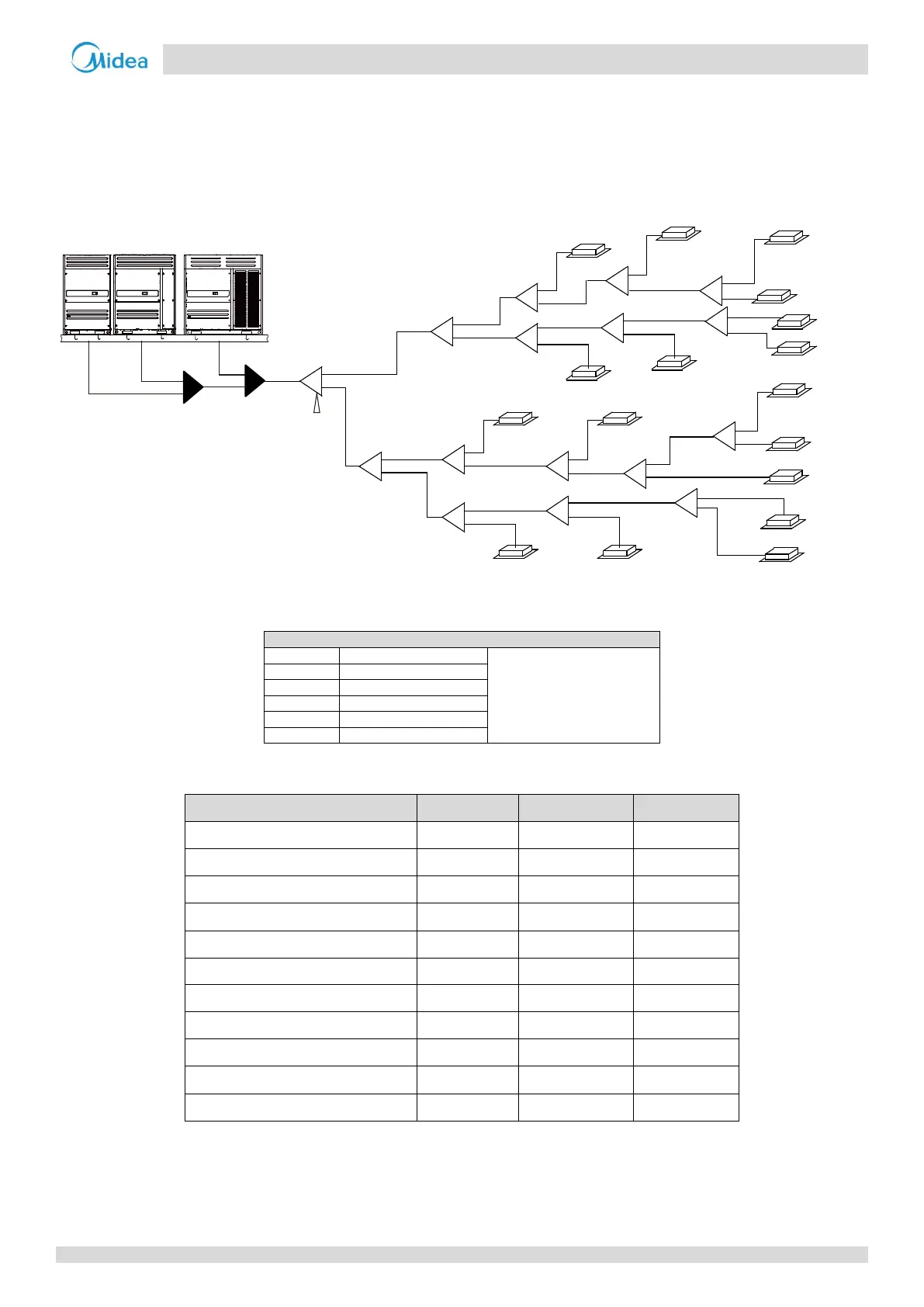
Tables 3-4.4 to 3-4.8, below, specify the required pipe diameters for the indoor and outdoor piping. The main pipe (L
1
) and
first indoor branch joint (A) should be sized according to whichever of Tables 3-4.4 and 3-4.5 indicates the larger size.
Figure 3-4.3: Selecting piping diameters
Figures in parentheses indicate
indoor unit capacity indexes.
Table 3-4.4: Main pipe
1
(L
1
), indoor main pipes (L
2
to L
16
) and indoor branch joint kits
Total capacity indexes of indoor units
168 ≤ Capacity indexes < 224
224 ≤ Capacity indexes < 330
330 ≤ Capacity indexes < 470
470 ≤ Capacity indexes < 710
710 ≤ Capacity indexes < 1040
1040 ≤ Capacity indexes < 1540
1540 ≤ Capacity indexes < 1800
1800 ≤ Capacity indexes < 2450
2450 ≤ Capacity indexes < 2690
Notes:
1. The main pipe (L
1
) and first indoor branch joint (A) should be sized according to whichever of
Tables 3-4.4 and 3-4.5 indicates the larger size.
N1
(140)
N4(140)
N9
(112)
N10
(140)
N12
(28)
N13
(140)
N16
(56)
N15
(140)
N3(71)
N7(28)
N6
(140)
N8(140)
N14
(56)
N17
(140)
A
B
I
J
N
K
O
C
F
H
E
L1
L2
L3
L5
L7
L8
L11
L12
L13
L15
L14
L16
L9
a
c
d
f
g
h
j
l
m
n
o
p
q
k
S
R
g1
g2
g3
G1
D
N2
(140)
b
L4
N5
(112)
G
L6
e
N11
(71)
i
L
L10
M
P
W3
(16)
W2
(22)
W1
(26)
 Loading...