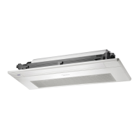
3) Disconnect following 6
pieces of connection wires
and connectors between
IPM and other parts.
CN3(red)
CN2(black)
U(blue),V(red),W(black)
CN9(10p,white)
CN8,CN5(3p)
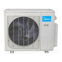
4) Remove the 4 screws and
unfix the 4 hooks and then
remove the IPM module
board.
5) Disconnect the
connectors and wires
connected from PCB and other
parts.
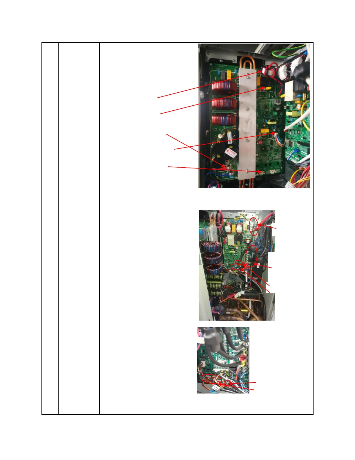
Connectors:
CN8: Discharge temperature sensor
(2p,white)
CN12:Heatsink temperature
sensor(2p,red)
CN9:T3/T4 temperature sensor
(2p/2p,white)
CN11:T2B-A,B,C,D,E temperature
sensor (2p/2p/2p/2p/2p,white)
CN15/CN23/CN26/CN30/CN33:
Electronic expansion valve
(6p/6p/6p/6p/6p,red)