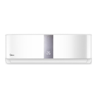
What to do if my Midea AURORA ONOFF Air Conditioner unit does not respond to the remote?
- BBrian BrownAug 1, 2025
If the Midea Air Conditioner unit does not respond to the remote, the indoor PCB requires replacement.
What to do if my Midea AURORA ONOFF Air Conditioner unit does not respond to the remote?
If the Midea Air Conditioner unit does not respond to the remote, the indoor PCB requires replacement.
General safety measures for preventing injury and damage during operation and maintenance.
Safety procedures for working with systems containing flammable refrigerants, including checks and work practices.
Lists indoor and outdoor unit models, capacities, and power supply details for identification.
Specifies connection pipe limits and elevation requirements for optimal performance.
Provides wiring schematics for indoor and outdoor units across various models for installation.
Explains the meaning of various symbols and indicators displayed on the unit's interface.
Details built-in safety mechanisms like compressor delay, fan speed shutoff, and sensor redundancy.
Describes core operational modes such as Cooling, Heating, Fan-only, and Auto modes.
Covers supplementary features like 8°C heating, self-clean, follow me, and silence modes.
Procedures for initial system setup, including leak testing and evacuation.
Steps for safely adding refrigerant to the system to ensure proper operation.
Procedures for recovering refrigerant and preparing the system for re-installation.
Provides physical dimensions (W, D, H) for indoor units based on their capacity.
Instructions for safely removing the indoor unit's front panel.
Procedures for accessing and disconnecting electrical components within the unit.
Steps to remove the evaporator coil from the indoor unit assembly.
Guide for disassembling and removing the fan motor and fan assembly.
Instructions for removing the stepping motor that controls the louvers.
Procedure for disconnecting and removing the condensate drain hose.
A table listing outdoor unit models, panel types, and PCB board information.
Detailed dimensional drawings for various outdoor unit panel plates.
Procedures for removing front, top, and side panels of the outdoor unit.
Instructions for accessing and removing electrical components like PCB boards and wiring.
Guide for removing the fan and fan assembly from the outdoor unit.
Procedure for removing the outdoor unit's fan motor.
Instructions for removing the sound insulation material from the outdoor unit.
Steps to detach and remove the four-way valve assembly.
Detailed procedure for safely removing the compressor unit.
Essential safety warnings and precautions before performing troubleshooting procedures.
Explains indoor unit error codes and provides initial troubleshooting steps.
A form for documenting customer complaints and unit failure details.
Procedure to access and display unit operational data and sensor readings.
Common operational issues and troubleshooting steps when no error code is present.
A quick reference table mapping error codes to likely faulty parts for replacement.
In-depth diagnosis and solutions for specific error codes displayed by the unit.
Specific procedures for checking critical components like sensors and fan motors.
Reference table for temperature sensor resistance values at various temperatures.
Resistance value table for TP temperature sensors used in specific unit models.
Charts detailing system pressures for cooling and heating modes with different refrigerants.
| Brand | Midea |
|---|---|
| Model | AURORA ONOFF Series |
| Category | Air Conditioner |
| Language | English |


