Appendix A
Preva
123
FIGURE 134
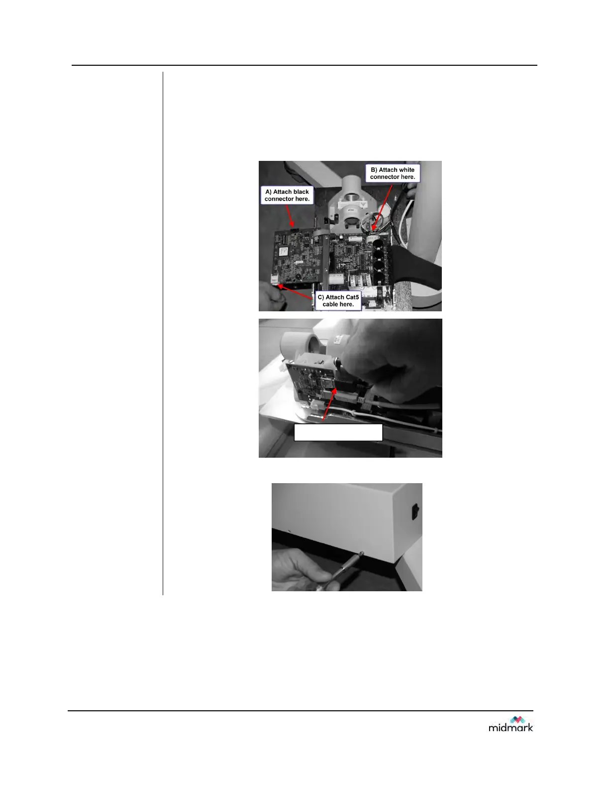
18. Remove the screw that locks down the Logic board. Swing out the Logic
Board and connect the three connections as shown below.
A) Black connector (Feedback from tubehead)
B) White connector (Power to tubehead)
C) Cat5 (network cable)
D) USB (for Sensor ready units)
FIGURE 135
19. Attach the control unit cover.
D) Attach USB Cable here