Appendix A
Preva
124
FIGURE 136
FIGURE 137
FIGURE 138
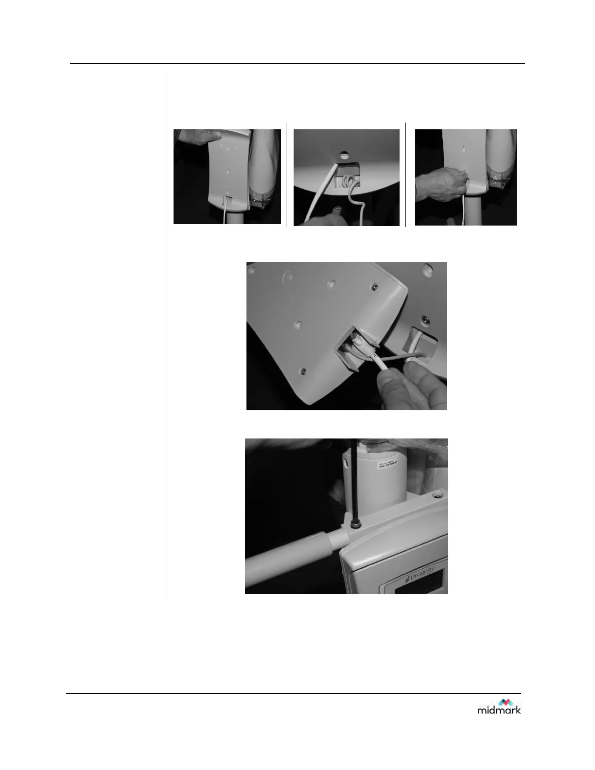
20. Feed the Cat5 cable through the Operator Panel Cradle. Feed remote
exposure cable through the bottom of cradle. NOTE: Allow a few coils
of slack inside for strain relief. Attach the cradle with supplied
hardware.
FIGURE 139
21. Connect Cat5 cable and remote switch cable to the Operator Panel.
Mount the Operator Panel into cradle.
FIGURE 140
22. Install the mobile unit handle with the supplied hardware.