Optional Installation Procedures
Preva
62
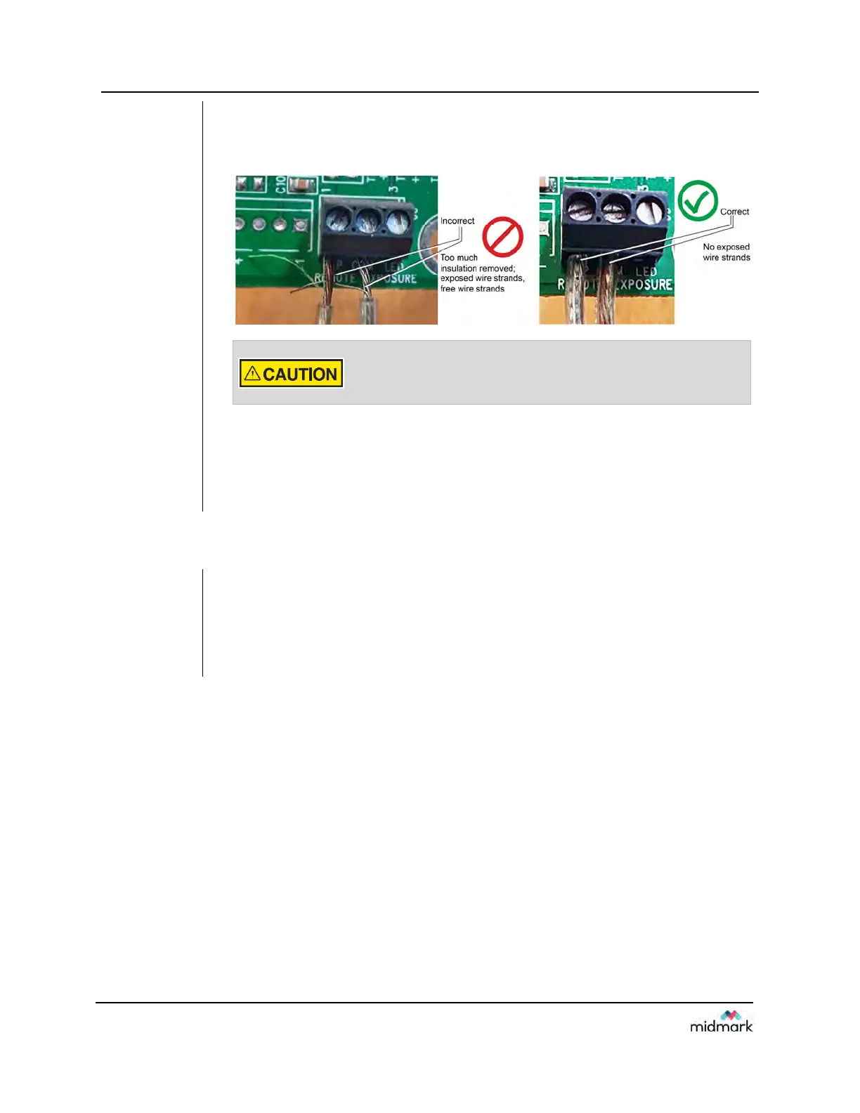
Figure 48
Correctly
connecting
wires to the
terminal
block
4. Use a small flat-head screwdriver to connect the remote exposure switch wires to
the “EXP” and “COM” terminals of terminal block J2. It is critical that there be no
exposed wire strands outside the terminal block (as shown the photograph on the
right).
Theexposureswitchwiresmustbeconnectedtotheterminalblock
withnoexposedstrandsofwire.Exposedwirescanshortcircuitand
causeunintendedexposuretoradiation.
5. Swing the logic board closed and secure it with the locking screw
6. Replace the control unit cover.
7. Follow the manufacturer’s directions to connect the two-way switch to the other
ends of the wires.
Installing the 12 Inch [30 CM] Cone (30-A2200)
The Preva Dental X-ray System is factory set for use with the standard supplied 8 inch
[20 cm] Cone. The 12 inch [30 cm] Cone (30-A2200) is recommended when using
parallel film positioning techniques. Using the longer cone requires longer exposure
times. See the System Configuration section of this manual on page 63 or setting the
system to use the longer cone.