10
Chapter 1: Introduction & Overview GR8
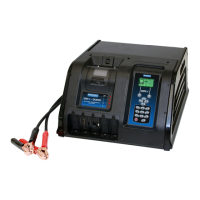
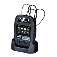
Charger Cables
The two connectors for the charger cables are located on
the back of the unit. Three screws are included to secure the
cables.
Plug the small connector into the small socket (A) on the back
of the unit.
A
B
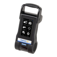
1. Plug the large connector (B) into the large socket while plac-
ing the protective cover (C) against the back of the unit.
C
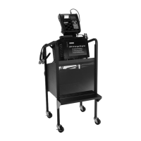
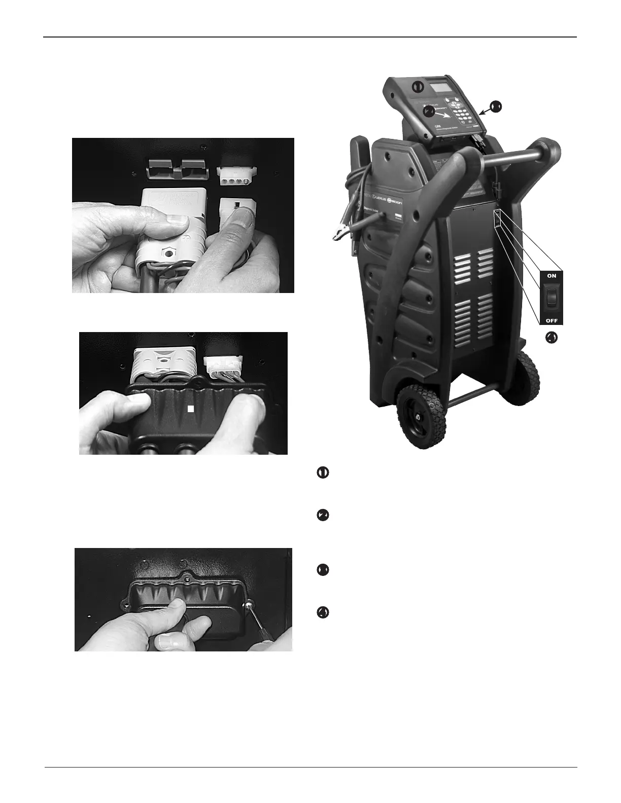
2. Center the three holes in mounting bracket over the bolts,
and lower the bracket onto the charger. Reinstall the hard-
ware in this order: the at washer rst, the lock washer
next, and the hex nut last. Tighten the nuts securely.
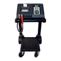
3. Insert the screws through the holes in the cover and se-
curely tighten the screws.
The installation is now complete.
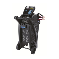
Connecting AC Power
Plug in the power cord on the back of the unit
.
Plug the
charger into a dedicated, grounded nominal 16-amp or higher
AC outlet. Press the power switch to the ON position.
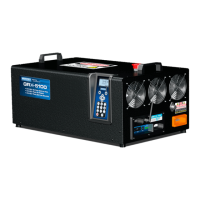
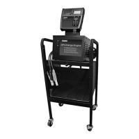
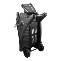
Front of GR8
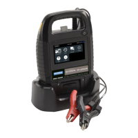
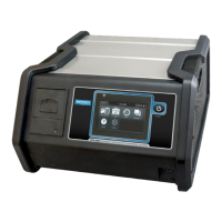
Control Module
Backlit graphical display and keypad for data entry.
STATUS light
Lights in conjunction with beeping alarm to indicate
transitions and warnings
.
Data Card slot
For data storage and future software updates.
ON/OFF Switch
Turns power on and o to the charger.