Installation
*INSTALLATION*
48
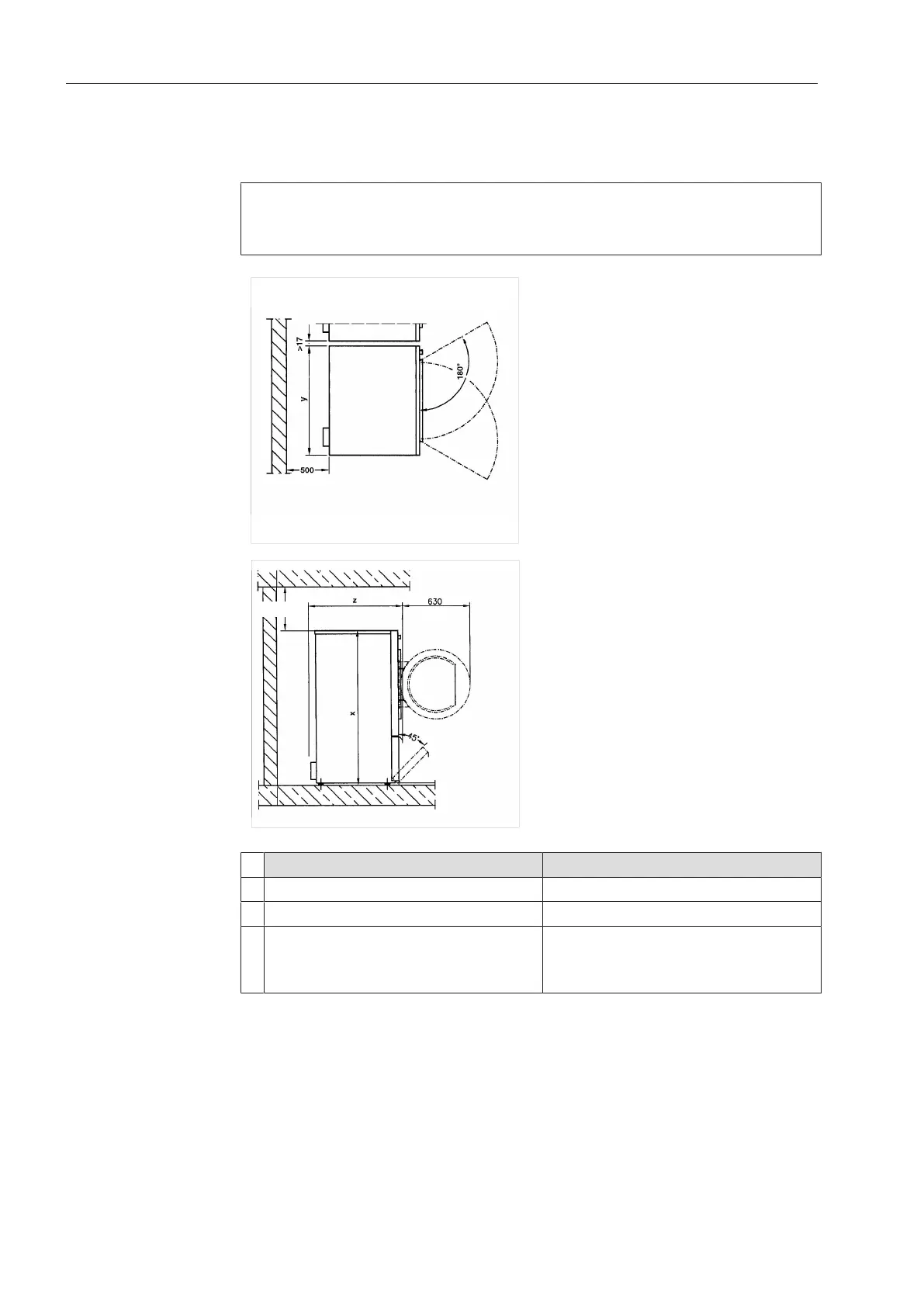
Installing the tumble dryer
Place the tumble dryer on a perfectly level, secure, and horizontal
surface that is able to withstand the specified floor load.
The floor load created by the tumble dryer is concentrated and trans-
ferred to the installation surface via the screw feet. A base is not re-
quired. However, an uneven floor surface must be compensated for.
(24 13/16")
> 300
(> 11 13/16")
PDR514/518/522/914/918/922 PDR528/544/928/944
x 55 1/8" (1,400mm) 64 9/16" (1,640mm)
y 35 11/16" (906mm) 47 1/2" (1,206mm)
z PDR514/914: 33 9/16" (852mm)
PDR518/918: 40 3/4" (1,035mm)
PDR522/922: 45 13/16" (1,164mm)
PDR528/928: 40 1/16" (1,018mm)
PDR544/944: 54 1/2" (1,384mm)
To facilitate any future maintenance work, a maintenance corridor
with a width of at least 19 11/16" (500mm) must be set up behind
the machine and must be accessible at all times. The distance be-
tween the machine and any walls must not fall below the specified
minimum values.
Adjust the tumble dryer screw feet until the machine is level. After
the machine has been aligned, screw the washers tightly to the base
plate using a screwdriver.