Installation
*INSTALLATION*
63
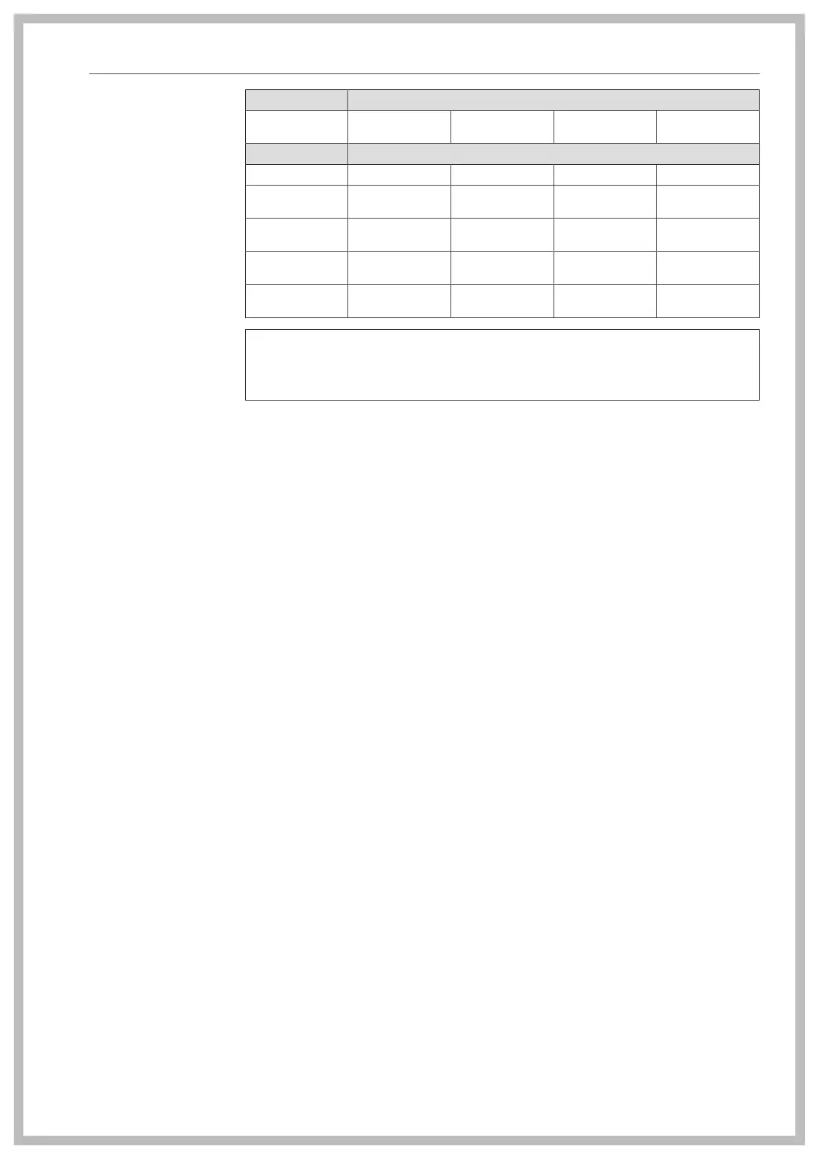
Liquid propane
Liquid propane Length of gas line
16' 4 7/8" (5 m) 32' 9 11/16" (10
m)
65' 7 3/8" (20 m) 164' 1/2" (50 m)
Internal diameter Maximum flow rate
3/8" (10 mm) 2.87 lb/h (1.3 kg/h) 2.2 lb/h (1.0 kg/h) - -
1/2" (12 mm) 4.41 lb/h (2.0 kg/
h)
3.31 lb/h (1.5 kg/h) 2.2 lb/h (1.0 kg/h) -
5/8" (16 mm) 8.82 lb/h (4.0 kg/
h)
6.61 lb/h (3.0 kg/
h)
4.41 lb/h (2.0 kg/
h)
3.31 lb/h (1.5 kg/h)
7/8" (22 mm) 19.84 lb/h (9.0 kg/
h)
14.33 lb/h (6.5 kg/
h)
9.92 lb/h (4.5 kg/
h)
6.61 lb/h (3.0 kg/
h)
1 1/16" (27 mm) - 26.46 lb/h (12.0
kg/h)
17.64 lb/h (8.0 kg/
h)
11.02 lb/h (5.0 kg/
h)
Exhaust gas evacu-
ation ducts
Gas-heated MieleTumble Dryers are type B
22
gas fuel-burning in-
stallations without flow safeguarding equipment, and with a fan be-
hind the heater.
- The mixtures of exhaust gas and air that are emitted by gas-heated
tumble dryers must be evacuated through a suitable chimney and
out into the atmosphere via the roof.
- Exhaust air evacuation ducts and exhaust gas evacuation ducts
must be kept as short as possible. The evacuation ducts must rise
vertically up to the flue.
- Only materials that are resistant to heat and sooting may be used.
- A condensate drain must be placed at the lowest point of the ex-
haust ducting. The condensate must be drained via a water collec-
tion tray or a floor drain positioned in an appropriate location. No fil-
ters or grilles may be fitted in the pipeline. The exhaust air or ex-
haust gas ducting must be installed leak-tight.
Compliance with the latest guidelines for approving exhaust gas sys-
tems containing low-temperature exhaust gases must be assured.
Exceptions
1. Where it is not possible for evacuation to take place through a
single duct, appropriate measures must be taken to ensure that
the exhaust gas/air mixture from the machine is not able to enter
the room in which the machine is located via the exhaust duct
for other machines (e.g., through the use of baffles and merged
lines that do not hinder the flow). When selecting and installing
equipment that will not hinder the flow, it is important to ensure
that high pressure cannot arise at the side that is not being oper-
ated. Machines fitted with fans must not be connected to the
same vent flue as those without fans.
2. When evacuating the exhaust gas/air mixture through the exte-
rior wall, no dangers or unreasonable nuisance may arise.
3. With a combined line, the exhaust air ducts for the individual
machines must be installed horizontally in the combined line in a
way that does not hinder the flow. The cross-section of the vent
flue must not be smaller than the cross-section of the combined
 Loading...