Pull the cover in the opposite direction from the device to remove it.
Reassemble.
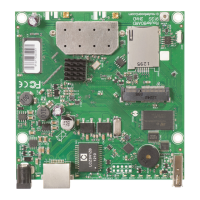
Expansion slots and ports
Built-in 2 GHz wireless access point module, AP/station/bridge/p2p modes are supported.
One 10/100 Ethernet port, supporting automatic cross/straight cable correction (Auto MDI/X). Either straight
or crossover cable can be used for connecting to other network devices. The ethernet port accepts 9-30 V
DC powering from a passive PoE injector.
miniPCIe slot and SIM slot (can’t be used separately) to be used with a 3G/4G/LTE modem (some kits
include it).
MiniPCIe slot usage
The device is equipped with a miniPCIe slot (a kit with preinstalled modem also available) to be used with a
3G/4G/LTE modem. A SIM slot is provided for use together with a miniPCIe modem. SIM slot is not used
separately.
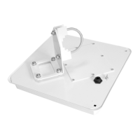
To install the miniPCIe module, remove both screws below the power jack and slide out the wAP PCB board. Insert
the miniPCIe modem, and secure it with two Philips screws which are already in place.
Attach the grey uFL connector to the MAIN antenna connector of the modem, attach the black cable to the other (or
AUX) connector. It is possible to use external antennas for the modem, two SMA mounting holes are provided next
to the reset button, or if you prefer to attach antennas to the case directly, SMA antennas can be mounted on the
bottom of the case if you remove the two plastic hole covers first.
After you have reinserted the wAP board into the case and secured it with the screws that were removed earlier,
slide in the SIM card from your mobile operator into the SIM slot, with the chip facing up. The slot accepts miniSIM
(2FF). The SIM slot protects the SIM card from falling out with a plastic latch. You can press the latch and then pull
the SIM out using tweezers or a similar tool.
Buttons and jumpers
The reset button has three functions:
Hold this button during boot time until LED light starts flashing, release the button to reset RouterOS configuration (total 5 seconds).
Keep holding for 5 more seconds, LED turns solid, release now to turn on CAP mode. The device will now look for a CAPsMAN server (total 10 seconds).
Or Keep holding the button for 5 more seconds until LED turns off, then release it to make the RouterBOARD look for Netinstall servers (total 15 seconds).
Regardless of the above option used, the system will load the backup RouterBOOT loader if the button is pressed before power is applied to the device. Useful for RouterBOOT
debugging and recovery.
Configuration
We recommend clicking the "Check for updates" button and updating your RouterOS software to the latest version to ensure the best performance and stability. RouterOS includes
many configuration options in addition to what is described in this document. We suggest visiting the RouterOS documentation page to get yourself accustomed to the possibilities:
https://mt.lv/help .
In case IP connection is not available, the Winbox tool (https://mt.lv/winbox ) can be used to connect to the MAC address of the device from the LAN side (all access is blocked from
the internet port by default).
It is possible to boot the device from a network, for reinstalling RouterOS for recovery purposes. This can be done from the first Ethernet port. See above how to do this.
Operating system support
The device supports RouterOS software version 6.46. The specific factory-installed version number is indicated in the RouterOS menu /system resource. Other operating systems
have not been tested.
Notice
The Frequency band 5.470-5.725 GHz isn’t allowed for commercial use.
In case WLAN devices work with different ranges than the above regulations, then a customized firmware version from the manufacturer/supplier is required to be applied to
the end-user equipment and also prevent the end-user from reconfiguration.
For Outdoor Usage: End-user requires approval/license from the NTRA.
Datasheet for any device is available on the official manufacturer website.
Products with the letters “EG” at the end of their serial number have their wireless frequency range limited to 2.400 – 2.4835 GHz, the TX power is limited to 20dBm (EIRP).
Products with the letters “EG” at the end of their serial number have their wireless frequency range limited to 5.150 – 5.250 GHz, the TX power is limited to 23dBm (EIRP).
Products with the letters “EG” at the end of their serial number have their wireless frequency range limited to 5.250 – 5.350 GHz, the TX power is limited to 20dBm (EIRP).
Please make sure the device has a lock package (firmware version from the manufacturer) which is required to be applied to the end-user equipment to prevent the end-user
from reconfiguration. The product will be marked with country code “-EG”. This device needs to be upgraded to the latest version to ensure compliance with local authority
regulations! It is the end users responsibility to follow local country regulations, including operation within legal frequency channels, output power, cabling requirements, and
Dynamic Frequency Selection (DFS) requirements. All MikroTik radio devices must be professionally installed.
 Loading...