02 October 2006
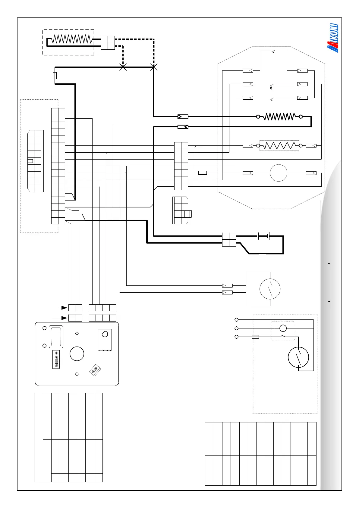
Mikuni Heating (UK) Ltd. MY30 Wiring Diagram
using solid state thermostat
GlowResistor
24VModels
Only
Notes:
1.Theglowresis
tor isfittedon
24Vheatersonly. Thisisa
'dropper'resistor tore
ducethevoltageontheglowplugto
12V.
2. *Fuse: Thisisa20mmglassfuse
toprotect the airmotor
.
12V=10A. 24V=8A
3. Overheat Trips: Reset buttons
toprotect the heater ifthe
ductinggetsb
lockedetc
M
Motor Resistor
7 10 13
14 15 16 2
Glowplug
Overheat Trip
8
8
Overheat Trip
Flame Sensor
14
13
3
3 4
4
ElectronicThermostat
1
234
+
_
2
2
13
7
15
10
14
13
10
14
7
15
Motor
*Fuse
10
7
Control Box
1
1
1
1
2
2
3
3
3
3
6
6
7
7
10
10
11
11
13
13
14
14
15
15
16
16
17
17
20
20
21
21
14
15 16
21
2
13 1
1
3
10
3
17
20
6
11
7
Fuel SolenoidPump
10
11
Fuse 25A
Fuse 30A
12 Or 24V DC.
1 2
21
Heater Body
Heater
Plug layout
152
13 15
+
-
1
2
3
4
1
2
21
6
14
20
Thermostat terminal blocks
Mikuni cable n
umbers
Cable Ref
1
2
3
6
7
10
11
13
14
15
20
21
Cable Colour
Red
Black
White
Red/Yellow
Green
Yellow/Red
Black/White
Brown
Blue/Yellow
Red
White
Green
FUEL SOLENOID
VALVE.
RELAY
FUSE 3 A.
OPTIONAL ELECTRIC FUEL
VALVE KIT.
+12/24v
No 6
Neg
+
-
1
2
3
4
Red
Black
Green
Red/Yellow
Blue/Yellow
White
+12/24 Volts
Negative
Cold Air
Switch return
Heat
Hi Lo Heat
Hi Lo Heat
Cable Colour Function
Thermostat wiring
-9-
 Loading...