EasyManua.ls Logo

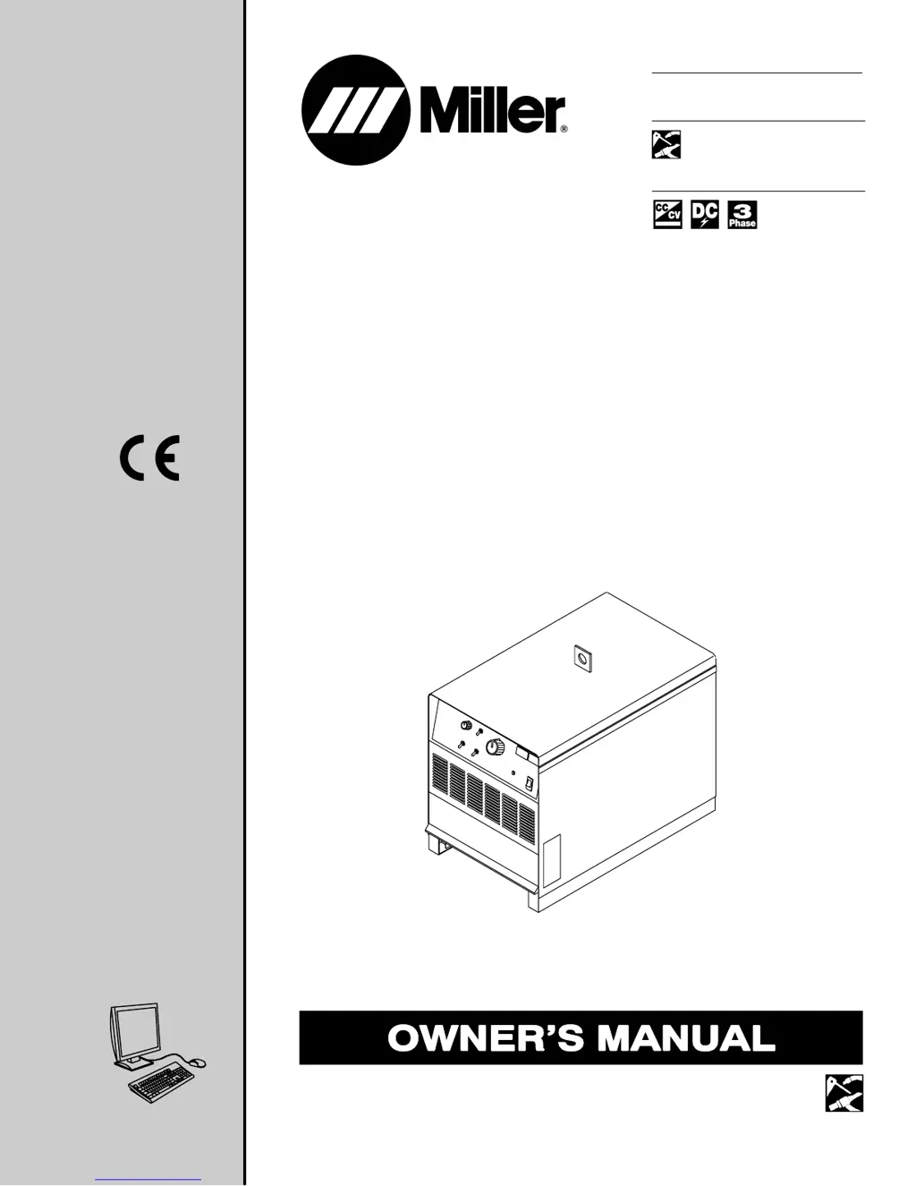
Miller Electric Dimension 652 - User Manual

Miller Electric Dimension 652
40 pages
Print Icon
To Next Page IconTo Next Page
Loading...
652 and 812
Processes
Description
Multiprocess Welding
Arc Welding Power Source
OM-278 163 769AC
200708
Dimension
Visit our website at
www.MillerWelds.com
File: Multi-Process

Table of Contents

Questions and Answers

  • M
    Misty FergusonJul 28, 2025
    What to do if my Miller Electric Dimension 652 has no weld output but the power light is on?
    • Z
      zjimenezJul 28, 2025
      If your Miller Electric Welding System shows no weld output but the power switch light is on, the unit may have overheated. Allow the unit to cool down with the fan running. Also, if you're using a remote control, ensure the Output (Contactor) switch is in the Remote position and the remote is properly connected. If not using a remote, put the switch in the On position. The remote control itself may need to be checked, repaired, or replaced.

Summary

SECTION 1 - SAFETY PRECAUTIONS

1-1. Symbol Usage

Explains the meaning of symbols used in the manual for hazard identification.

1-2. Arc Welding Hazards

Covers general hazards associated with arc welding processes and equipment.

1-3. Additional Symbols For Installation, Operation, And Maintenance

Details specific hazard symbols for unit installation, operation, and maintenance.

SECTION 4 - INSTALLATION

4-2. Duty Cycle And Overheating

Explains duty cycle percentages and precautions against overheating.

4-11. Mig (GMAW) Cable Connections

Specific instructions for connecting cables for MIG (GMAW) welding.

4-12. Mig (GMAW) And Flux Cored (FCAW) Cable Connections

Instructions for connecting cables for MIG (GMAW) and Flux Cored (FCAW) welding.

4-13. TIG (GTAW) Cable Connections

Specific instructions for connecting cables for TIG (GTAW) welding.

4-18. Connecting Input Power

Detailed steps for safely connecting the unit to the input power supply.

SECTION 5 - OPERATION

5-1. Controls (Non CE Models)

Explains the controls and their functions for non-CE models of the unit.

5-2. Controls (CE Models)

Explains the controls and their functions for CE models of the unit.

SECTION 6 - MAINTENANCE & TROUBLESHOOTING

6-4. Troubleshooting

Provides a guide to diagnose and resolve common problems with the welding unit.

SECTION 7 - ELECTRICAL DIAGRAM

SECTION 8 - PARTS LIST

Miller Electric Dimension 652 Specifications

General IconGeneral
BrandMiller Electric
ModelDimension 652
CategoryWelding System
LanguageEnglish

Related product manuals