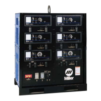
EasyManua.ls Logo

Miller Electric MARK VIII-2 User Manual

Miller Electric MARK VIII-2
44 pages
To Next Page IconTo Next Page
Page #1 background imageLoading...
Page #1 background image
Processes
OM-218 029 920Z
July 2005
MARK VIII-2
Visit our website at
www.MillerWelds.com
Description
Air Carbon Arc (CAC-A) Cut-
ting and Gouging
TIG (GTAW) Welding
Stick (SMAW) Welding
MIG (GMAW) Welding
Arc Welding Power Source
With Optional Equipment:
Air Plasma Cutting
and Gouging
Flux Cored (FCAW) Welding
®

Table of Contents

Questions and Answers:

Miller Electric MARK VIII-2 Specifications

General IconGeneral
BrandMiller Electric
ModelMARK VIII-2
CategoryWelding System
LanguageEnglish

Summary

SECTION 1 - SAFETY PRECAUTIONS - READ BEFORE USING

1-1. Symbol Usage

Explains symbols used for warnings and notes in the manual.

1-2. Arc Welding Hazards

Outlines potential dangers associated with arc welding processes.

1-3. Additional Symbols For Installation, Operation, And Maintenance

Details extra safety symbols for equipment setup, use, and upkeep.

SECTION 2 - CONSIGNES DE SÉCURITÉ - LIRE AVANT UTILISATION

2-2. Dangers relatifs au soudage à l'arc

Outlines potential dangers associated with arc welding in French.

2-3. Dangers supplémentaires en relation avec l'installation, le fonctionnement et la maintenance

Details extra safety hazards for equipment setup, use, and upkeep in French.

SECTION 3 – SPECIFICATIONS

3-3. Duty Cycle And Overheating

Explains duty cycle ratings and overheating protection for the unit.

SECTION 4 – INSTALLATION

4-5. Connecting Weld Output Cables

Steps for correctly connecting weld output cables to the unit terminals.

4-6. Connecting To Weld Output Terminals

Safety warnings and procedures for connecting cables to output terminals.

4-10. Connecting Input Power

Procedures for connecting the main input power to the unit.

4-11. Electrical Service Guide

Guide for electrical service requirements like voltage and conductor size.

SECTION 5 – OPERATION

5-1. Controls

Identifies and explains the main controls on the unit's front panel.

5-2. Amperage Adjustment Controls

Details how to adjust amperage using front panel and remote controls.

5-3. Power Switch Push Buttons And Pilot Light

Explains the function of the power switch and pilot indicator light.

SECTION 6 – MAINTENANCE & TROUBLESHOOTING

6-2. Overload Protection

Explains overload protection devices like circuit breakers and fuses.

6-4. Troubleshooting

Provides solutions for common problems and operational issues.

SECTION 8 – SELECTING AND PREPARING TUNGSTEN ELECTRODE

SECTION 9 – GUIDELINES FOR TIG WELDING (GTAW)

Related product manuals