Do you have a question about the Miller Electric Trailblazer Pro 350 and is the answer not in the manual?
Details risks associated with arc welding, including electric shock, burns, fumes, and fire.
Outlines dangers related to the engine, such as fuel, steam, coolant, moving parts, and battery.
Covers additional symbols for safe installation, operation, and maintenance procedures.
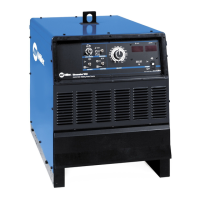
Details the technical specifications for welding output, generator power, and engine.
Explains duty cycle percentages and the risks of overheating the unit.
Shows voltage and amperage output capabilities for DC and AC Stick welding modes.
Displays voltage and amperage output capabilities for AC and DC TIG welding modes.
Illustrates voltage and amperage output capabilities for DC/CV MIG welding.
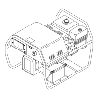
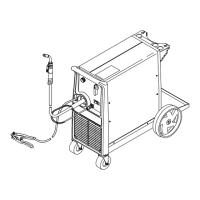
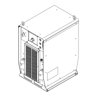
Provides instructions and safety precautions for installing the welding generator unit.
Details essential checks and fluid levels before starting the engine for the first time.
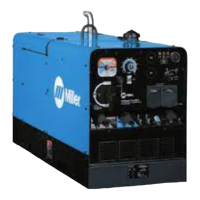
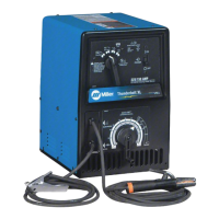
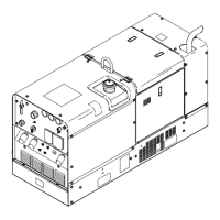
Identifies and locates the main controls on the welding generator's front panel.
Provides detailed explanations of each control's function and operation.
Outlines routine maintenance tasks and their recommended service intervals.
Covers oil changes, filter replacements, and draining the fuel system.
Instructions for checking and maintaining the engine's cooling system, including coolant.
Procedures for adjusting idle and weld/power engine speeds.
Provides solutions for common welding and generator power issues.
| Duty Cycle | 100% at 300 Amps |
|---|---|
| AC Generator Output (Peak) | 12, 000 Watts |
| Engine | Kohler CH 740 |
| Fuel Type | Gasoline |
| Fuel Tank Capacity | 12 Gallons |
| Type | Engine-Driven Welder/Generator |
| Welding Amperage Range | 30-350 Amps |
| Open Circuit Voltage | 80 Volts |
| AC Generator Output (Continuous) | 10 kW |
| Dimensions | 36 inches |
| Process | Stick, TIG, MIG, Flux-Cored |
| Output Range | 30-350 Amps |