Do you have a question about the Miller Electric BLUE STAR 6000 TM-499C and is the answer not in the manual?
| Brand | Miller Electric |
|---|---|
| Model | BLUE STAR 6000 TM-499C |
| Category | Welding System |
| Language | English |
Explains symbols indicating potential hazards in procedures and general hazard indicators.
Details general safety hazards and precautions for servicing the unit to prevent injury.
Lists chemicals known to cause cancer or birth defects as required by California law.
Discusses electromagnetic fields and potential exposure minimization during welding.
Defines common symbols used in the manual for components and functions.
Details technical specifications for welding, power output, and engine types.
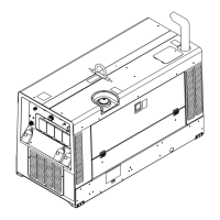
Provides physical dimensions, weight, and safe operating angles for the unit.
Graphs showing fuel consumption for Kohler and Honda engines under various loads.
Explains duty cycle and its impact on unit longevity and warranty coverage.
Graphs illustrating AC power output (voltage vs. amperage) available at receptacles.
Graphs showing minimum and maximum voltage and amperage output capabilities.
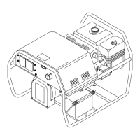
Instructions for safely installing the generator, including airflow clearance requirements.
Procedures for grounding the generator frame to a vehicle for electrical safety.
Guidelines for grounding the generator when connecting to building wiring systems.
Pre-operation checks for Kohler engine models, including fuel and oil levels.
Pre-operation checks for Honda engine models, including fuel and oil levels.
Steps for correctly connecting the battery to electric-start models.
Instructions for connecting weld cables securely to the output terminals.
Chart and guidelines for selecting appropriate weld cable sizes based on amperage and length.
Explanation and illustration of all controls for Kohler-powered units.
Illustration of controls for Honda-powered units, referencing detailed descriptions.
Detailed description of controls for Honda-powered units, referencing illustrations.
Details the functionality and components of the USA standard generator power panel.
Shows various optional generator power panels available for different regions.
Table outlining power ratings and circuit protection for different generator power panels.
Provides wiring instructions for the optional 120/240 Volt Twistlock Plug (NEMA L14-30P).
Explains the maintenance schedule indicated by labels on the unit based on operating hours.
Outlines routine maintenance tasks and their recommended intervals based on operating hours.
Describes the overload protection mechanism specific to Honda-powered units.
Instructions for adjusting engine speed for Kohler units to ensure proper operation.
Instructions for adjusting engine speed for Honda units to ensure proper operation.
Explains engine power source and rotor function in power generation.
Describes stator windings, rectifiers, stabilizer, and suppressor functions.
Details control board, current control, and shunt for managing weld output.
Covers circuit breakers, receptacles, HF filter, and output terminals.
General safety warnings related to electrical shock when working with the unit.
Tables listing common troubles and their remedies for welding and generator power issues.
Provides a circuit diagram for troubleshooting welding generator issues.
Lists test points and their expected voltage/resistance values for diagnostics.
Details testing procedures, information, and test point values for Control Board PC1.
Procedures to verify unit output and performance after maintenance or repair.
Outlines the general procedure for disassembling the welding generator.
Details the process of removing the rotor and reassembling the generator components.
Circuit and wiring diagrams for the main welding generator unit.
Circuit and wiring diagrams for various generator power panel configurations.
Circuit diagram for the PC1 control board.
Circuit diagram for the PC2 HF board.
Exploded view and parts list for the main assembly of Kohler units.
Lists and illustrates various generator power panels for different models.
Exploded view and parts list for the main assembly of Kohler/Honda units.
Lists and illustrates various generator power panels for different models.
Exploded view and parts list for the main assembly of later Kohler/Honda units.
Lists and illustrates various generator power panels for different models.
Exploded view and parts list for the main assembly of latest Kohler/Honda units.
Lists and illustrates various generator power panels for different models.
Table providing decimal equivalents for fractional measurements used in the manual.