Do you have a question about the Miller Electric Big Blue 300 and is the answer not in the manual?
Explains safety symbols and details hazards related to arc welding, engine, and compressed air.
Covers additional symbols for installation/maintenance, California warnings, safety standards, and EMF information.
Defines warning labels and various symbols used to convey important safety and operational information.
Explains the details provided on the manufacturer's rating label, including specifications and certifications.
Details the welding output, generator power ratings, and engine specifications for the unit.
Provides physical dimensions, volt-ampere curves, fuel consumption, and duty cycle information.
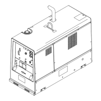
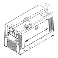
Covers procedures for installing, mounting, and securing the welding generator.
Details connecting the exhaust pipe, battery, weld output terminals, and remote controls.
Lists essential checks for the engine and related systems before starting the generator.
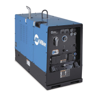
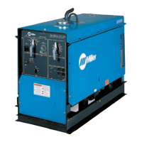
Identifies and describes the main controls and indicators on the generator's front panel.
Explains how to select welding processes, use Lift-Arc, and control voltage/amperage remotely.
Explains the function, capacity, and usage of the generator's auxiliary power outlets.
Outlines regular maintenance tasks, intervals, and references for the welding generator.
Provides common troubleshooting steps for welding, generator power, and engine issues, plus interprets help codes.
Presents detailed electrical circuit diagrams for the welding generator, aiding in system understanding.
Details procedures for engine break-in, including preventing wetstacking using load banks or resistance grids.
Guides on selecting equipment, grounding methods, and power requirements for connected devices.
Explains how to calculate power needs, start motors, and manage generator supply with various loads.
Lists parts for the main assembly, front panel, control panel, generator, and rectifier, with diagrams.
Details the terms and conditions of the manufacturer's limited warranty, including coverage periods and exclusions.
Provides contact information and resources for obtaining service and support for the equipment.
| Model | Big Blue 300 |
|---|---|
| Rated Output Duty Cycle | 100% |
| Open Circuit Voltage | 80 Volts |
| Fuel Type | Diesel |
| Frequency | 60 Hz |
| Type | Engine Driven Welding Generator |
| Rated Output | 300 Amps |