Do you have a question about the Miller Electric Big 40G and is the answer not in the manual?
Explains warning symbols and general safety precautions for hazards.
Details hazards like electric shock, arc rays, fumes, and fire from welding.
Covers risks from engine exhaust, heat, battery acid, explosion, and moving parts.
Discusses safety related to falling units, flying sparks, overheating, and static discharge.
Lists key safety standards and information on electromagnetic field effects.
Defines common symbols and terms used throughout the manual.
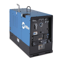
Provides key specifications for welding output, auxiliary power, and engine details.
Details physical dimensions, weight, operating angles, and fuel usage.
Explains duty cycle limits, overheating risks, and AC auxiliary power capabilities.
Shows minimum and maximum voltage/amperage output capabilities for different welding modes.
Covers generator placement, airflow, grounding, battery, and muffler installation.
Outlines daily checks for fluids, fuel, oil, and coolant before starting the engine.
Explains connecting weld cables to output terminals and selecting appropriate cable sizes.
Details connections for optional Remote 14 receptacle and terminal strip 3T.
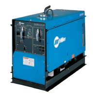
Identifies and describes the various controls located on the front panel of the welding generator.
Provides detailed explanations for each front panel control and indicator light.
Explains how to use the optional remote amperage control for adjusting settings.
Details the 120V receptacles, GFCI protection, and circuit breakers.
Describes the optional 240V receptacle, its protection, and output limits.
Provides instructions for connecting an optional auxiliary power plant, including wiring diagrams.
Outlines scheduled maintenance tasks and their intervals (e.g., oil change, filter replacement).
Details the information found on the maintenance label, including fluid capacities and service intervals.
Provides instructions for air filter maintenance and explains overload protection components.
Step-by-step guide for changing the engine oil and oil filter.
Instructions for replacing the fuel filter and cleaning the spark arrestor muffler.
Details how to adjust engine speed for welding and power output.
Explains setting idle speed and adjusting governor sensitivity for optimal performance.
Instructions for high-altitude carburetor adjustment and troubleshooting welding output issues.
Offers solutions for common problems related to auxiliary power output.
Lists common engine problems and their remedies, including starting and running issues.
Guides users on selecting auxiliary equipment and proper grounding methods.
Details grounding for building systems and how to calculate equipment power requirements.
Lists approximate starting and running watts for various industrial motors.
Provides power requirements for common farm/home and contractor equipment.
Explains calculating motor starting amperage and generator output limits.
Illustrates how to connect the generator for standby power during outages.
Provides charts for selecting appropriate extension cords based on load and length.
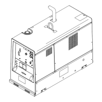
Exploded view diagram of the main assembly with numbered parts.
Exploded view of the generator component with numbered parts.
Lists parts for the main assembly, continuing from previous page.
Lists parts for the front panel and control box assemblies.
Exploded view of the front panel with components and part numbers.
Lists parts for the front panel, continuing from previous page.
Exploded view of the control box and its components with part numbers.
Information on contacting distributors and the terms of Miller's limited warranty.
Lists items and conditions not covered by the limited warranty.
Provides contact information for locating service distributors and agencies.
| Welding Current Range | 40-400 A |
|---|---|
| Output Current Range | 40-400 A |
| Duty Cycle | 100% at 300 A |
| Welding Processes | Stick (SMAW), TIG (GTAW) |
| Generator Output | 10, 000 Watts Peak |
| Auxiliary Power | 120/240V |