EasyManua.ls Logo

Miller Electric Big 40 C - User Manual

Miller Electric Big 40 C
90 pages
Print Icon
To Next Page IconTo Next Page
Loading...
Processes
Description
TIG (GTAW) Welding
Stick (SMAW) Welding
MIG (GMAW) Welding
Engine Driven Welding Generator
OM-4427 215 622L
200601
Visit our website at
www.MillerWelds.com
Flux Cored (FCAW) Welding
Air Carbon Arc (CAC-A)
Cutting and Gouging
File: Engine Drive
Big 40 C
Big 40 CX

Table of Contents

Questions and Answers

Summary

Section 1: Safety Precautions

Symbol Usage and General Warnings

Explains safety symbols and general hazard warnings.

Arc Welding and Fume Hazards

Details dangers of arc welding, fumes, gases, and arc rays.

Section 1: Engine, Fuel, and Cylinder Hazards

Engine, Fuel, and Battery Hazards

Covers risks associated with the engine, fuel, battery, and moving parts.

Welding Fire, Hot Parts, and Noise Hazards

Covers fire, hot parts, noise, magnetic fields, and flying metal hazards.

Section 1: Compressed Air and Operational Hazards

Compressed Air and Cylinder Hazards

Explains hazards related to compressed air, cylinders, and installation.

Operational Hazards and Warnings

Details risks from overheating, static discharge, flying sparks, and trailer tilting.

Section 1: Interference, Standards, and EMF Information

Interference and Proposition 65 Warnings

Addresses HF radiation, arc welding interference, and California Prop 65 warnings.

Safety Standards and EMF Information

Lists principal safety standards and EMF considerations.

Section 3: Definitions

Warning Label Definitions

Explains the meaning of warning labels found on the equipment.

Section 3: Manufacturers Rating Labels

Manufacturers Rating Labels

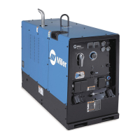
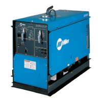
Details the specifications and ratings of the welding generator.

Section 3: Symbols and Definitions

Symbols and Definitions

Provides definitions for various symbols used in the manual.

Section 4: Specifications Overview

Weld, Power, and Engine Specifications

Lists detailed specifications for welding, power output, and engine.

Dimensions, Weights, and Operating Angles

Provides physical dimensions, weight, and safe operating angles.

Section 4: Volt-Ampere Curves (CC Models)

Volt-Ampere Curves For CC Models

Shows voltage and amperage output capabilities for CC models.

Section 4: Volt-Ampere Curves (CC;CV Models)

Volt-Ampere Curves For CC;CV Models

Displays voltage and amperage curves for CC/CV models in different modes.

Section 4: Fuel Consumption and Duty Cycle

Fuel Consumption

Illustrates typical fuel usage under weld or power loads.

Duty Cycle And Overheating

Explains duty cycle percentages and overheating risks.

Section 4: AC Generator Power Curves

AC Generator Power Curve

Shows generator power availability at 120V and 240V receptacles.

Optional Three-Phase Generator Curves

Details AC power curves for optional three-phase generators.

Section 5: Installation

Installing Welding Generator

Provides instructions for securely mounting the generator on vehicles.

Grounding Generator to Vehicle Frame

Explains proper grounding procedures for safety.

Section 5: Lifting Eye Usage

Using Lifting Eye

Details how to safely use the lifting eye for moving the unit.

Section 5: Generator Mounting

Mounting Welding Generator

Provides methods for mounting the generator using brackets or welding.

Section 5: Exhaust Pipe Installation

Installing Exhaust Pipe

Instructions for installing the exhaust pipe correctly.

Section 5: Battery Activation and Connection

Activating The Dry Charge Battery

Step-by-step guide for activating a dry charge battery.

Connecting The Battery

Instructions for correctly connecting the battery terminals.

Section 5: Engine Prestart Checks

Engine Prestart Checks

Details essential checks before starting the engine for safe operation.

Section 5: Weld Output Connections

Connecting To Weld Output Terminals

Explains proper connection of weld cables to output terminals.

Section 5: Cable Selection and Remote Amperage

Selecting Weld Cable Sizes

Provides guidelines for choosing appropriate weld cable sizes.

Connecting To Remote Amperage Adjust RC13

Details connecting a remote control for amperage adjustment.

Section 5: Remote 14 Receptacle Connection

Connecting To Remote 14 Receptacle RC14

Explains connecting remote controls to the RC14 receptacle.

Section 6: Operating CC Models

Front Panel Controls Overview (CC Models)

Identifies and locates front panel controls for CC models.

Section 6: CC Model Control Descriptions

Description of CC Model Front Panel Controls

Explains the function of each control on the CC model front panel.

Section 6: CC Model Remote and Arc Control

Remote Amperage Control On CC Models

Details how to set up and use remote amperage control.

Weld Control;Arc Condition Information

Explains how to adjust controls for different arc conditions.

Section 7: Operating CC;CV Models

Front Panel Controls Overview (CC;CV Models)

Identifies and locates front panel controls for CC/CV models.

Section 7: CC;CV Model Control Descriptions

Description of CC;CV Model Front Panel Controls

Explains the function of each control on the CC/CV model front panel.

Section 7: Process Switch and Remote Control

Process;Contactor Switch On CC;CV Models

Details the function of the process/contactor switch.

Section 7: CC;CV Remote Operation

Remote Voltage;Amperage Control On CC;CV Models

Explains remote voltage/amperage control setup for CC/CV models.

Section 8: Auxiliary Equipment Operation

120 Volt And 240 Volt Receptacles

Explains the use and safety of 120V and 240V receptacles.

Section 8: Optional Three-Phase Generator

Connecting To Optional Three-Phase Generator

Instructions for connecting optional three-phase generators.

Section 8: Optional Generator Receptacles

Optional Generator Power Receptacles

Details different optional generator power receptacles and their usage.

Section 9: Maintenance Overview

Maintenance Label

Explains the maintenance schedule indicated by the label.

Section 9: Routine Maintenance

Routine Maintenance

Outlines the routine maintenance schedule based on operating hours.

Section 9: Generator Brush Checking

Checking Generator Brushes

Provides steps for inspecting and replacing generator brushes.

Section 9: Air Cleaner Servicing

Servicing Air Cleaner

Details the procedure for cleaning or replacing the air cleaner element.

Section 9: Spark Arrestor Muffler Inspection

Inspecting And Cleaning Optional Spark Arrestor Muffler

Instructions for inspecting and cleaning the spark arrestor muffler.

Section 9: Engine Speed Adjustment

Adjusting Engine Speed On Models With Automatic Idle

Guides on adjusting engine speed for idle and weld/power.

Section 9: Fuel and Lubrication Servicing

Servicing Fuel And Lubrication Systems

Instructions for servicing fuel and lubrication systems, including oil and filters.

Section 9: Overload Protection

Overload Protection

Explains the function of various circuit breakers and fuses for overload protection.

Section 9: Troubleshooting (CC Models)

Troubleshooting (CC Models)

Provides troubleshooting steps for CC welding output issues.

Section 9: Troubleshooting (CC;CV Models)

Troubleshooting (CC;CV Models)

Provides troubleshooting steps for CC/CV welding output and controls.

Section 9: Troubleshooting (Generator Power)

Troubleshooting (Generator Power)

Troubleshooting common generator power output problems.

Troubleshooting (Optional Three-Phase Power)

Troubleshooting issues with optional three-phase generator power.

Section 9: Troubleshooting (Engine Issues)

Troubleshooting (Engine Issues)

Addresses common engine starting and running problems.

Section 10: Electrical Diagrams

CC Welding Generator Circuit Diagram

Presents the electrical circuit diagram for CC welding generators.

Section 10: CC;CV Welding Generator Circuit Diagram

CC;CV Welding Generator Circuit Diagram

Shows the electrical circuit diagram for CC/CV welding generators.

Section 11: Engine Run-In Procedures

Understanding Wetstacking

Explains wetstacking and its causes in diesel engines.

Section 11: Load Bank Run-In Procedure

Run-In Procedure Using Load Bank

Provides steps for performing a run-in procedure using a load bank.

Section 11: Resistance Grid Run-In Procedure

Run-In Procedure Using Resistance Grid

Details the run-in procedure using a resistance grid.

Section 12: Generator Power Guidelines

Equipment Selection and Grounding

Guides on selecting equipment and proper grounding for mobile units.

Grounding Generator to Truck or Trailer Frame

Explains proper grounding procedures for mobile generator units.

Section 12: Powering Building Systems and Equipment

Grounding When Supplying Building Systems

Instructions for grounding the generator when supplying building systems.

How Much Power Does Equipment Require?

Explains how to calculate power requirements for connected equipment.

Section 12: Approximate Power Requirements

Power Requirements for Industrial Motors

Lists approximate power requirements for various industrial motors.

Power Requirements for Farm;Home Equipment

Lists power requirements for farm and home equipment.

Section 12: Power Requirements for Contractor Equipment

Approximate Power Requirements For Contractor Equipment

Lists power requirements for contractor equipment.

Section 12: Motor Starting Power and Generator Supply

Power Required To Start Motor

Explains how to calculate motor starting amperage.

How Much Power Can Generator Supply?

Discusses load limits and starting motors with the generator.

Section 12: Standby Power and Extension Cords

Typical Connections To Supply Standby Power

Illustrates typical connections for supplying standby power.

Section 12: Extension Cord Selection

Selecting Extension Cord

Provides tables for selecting extension cords based on current and voltage.

Section 13: Parts List - Main Assembly

Figure 13-1. Main Assembly (Export Model Shown)

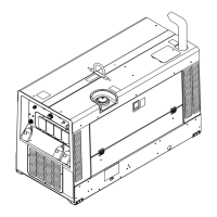
Exploded view and parts list for the main assembly.

Section 13: Parts List - Generator Components

Figure 13-6. Generator

Exploded view and parts list for the generator components.

Section 13: Parts List - Main Assembly Continued

Figure 13-1. Main Assembly (Continued)

Continues the parts list for the main assembly.

Section 13: Parts List - Main Assembly Continued

Figure 13-1. Main Assembly (Continued)

Continues the parts list for the main assembly.

Section 13: Parts List - Main Assembly Continued

Figure 13-1. Main Assembly (Continued)

Continues the parts list for the main assembly.

Section 13: Parts List - Main Assembly Continued

Figure 13-1. Main Assembly (Continued)

Continues the parts list for the main assembly.

Section 13: Parts List - CC Control Box

Figure 13-2. Control Box Assembly - CC Models

Exploded view and parts list for the CC model control box.

Section 13: Parts List - CC Control Box Continued

Figure 13-2. Control Box Assembly - CC Models (Continued)

Continues parts list for CC model control box.

Section 13: Parts List - CC;CV Control Box

Figure 13-3. Control Box Assembly - CC;CV Models

Exploded view and parts list for CC/CV model control box.

Section 13: Parts List - CC;CV Control Box Continued

Figure 13-3. Control Box Assembly - CC;CV Models (Continued)

Continues parts list for CC/CV model control box.

Section 13: Parts List - CC Front Panel

Figure 13-4. Panel, Front w;Components - CC Models

Exploded view and parts list for CC model front panel components.

Section 13: Parts List - CC Front Panel Continued

Figure 13-4. Panel, Front w;Components - CC Models (Continued)

Continues parts list for CC model front panel.

Section 13: Parts List - CC;CV Front Panel

Figure 13-5. Panel, Front w;Components - CC;CV Models

Exploded view and parts list for CC/CV model front panel components.

Section 13: Parts List - CC;CV Front Panel Continued

Figure 13-5. Panel, Front w;Components - CC;CV Models (Continued)

Continues parts list for CC/CV model front panel.

Section 13: Parts List - CC;CV Front Panel Continued

Figure 13-5. Panel, Front w;Components - CC;CV Models (Continued)

Continues parts list for CC/CV model front panel.

Section 13: Parts List - Generator Components

Figure 13-6. Generator

Exploded view and parts list for generator components.

Section 13: Parts List - Generator Components Continued

Figure 13-6. Generator (Continued)

Continues parts list for generator components.

Section 13: Parts List - Rectifier Assembly

Figure 13-7. Main Rectifier Assembly

Exploded view and parts list for the main rectifier assembly.

Section 13: Parts List - Wiring Harnesses

Wiring Harnesses

Lists various wiring harnesses and their included components.

Section 13: Parts List - Wiring Harnesses Continued

Wiring Harnesses (Continued)

Continues listing wiring harnesses and associated parts.

True Blue Limited Warranty

Warranty Periods and Coverage

Details warranty duration for different equipment types and components.

Warranty Exclusions

Lists conditions and situations not covered by the warranty.

Owners Record and Service Information

Owners Record Fields

Fields for recording model, serial, purchase date, and distributor information.

Contacting Miller for Service

Information on contacting distributors and service agencies for support.

Miller Electric Big 40 C Specifications

General IconGeneral
BrandMiller Electric
ModelBig 40 C
CategoryWelding System
LanguageEnglish

Related product manuals